 |
||
|
|
||
| |||||||||||||||
|
|
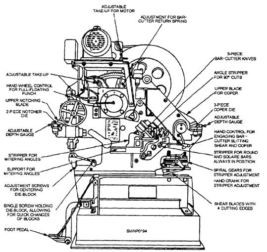
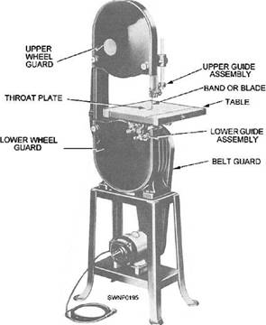
COMBINATION IRON WORKER The combination iron worker is likely the most valuable and versatile machine in a shop. The combination punch, shear, and coper (fig. 12-8) is capable of cutting angles, plates, and steel bars, and it can also punch holes. The size of the angles and plates that can be safely handled by the machine depends upon its capacity. It is manufactured in various sizes and capacities, and each machine has a capacity plate either welded or riveted on it. This guide should be strictly adhered to. The pressure and power the machine develops demand extreme caution on the part of the operator. VERTICAL BAND SAWS While the vertical band saw is designed primarily for making curved cuts, it can also be used for straight cutting. Unlike the circular saw, the band saw is frequently used for freehand cutting. The band saw has two large wheels on which a continuous narrow saw blade, or BAND, turns, just as a belt is turned on pulleys. The LOWER WHEEL, located below the WORKING TABLE, is connected to the motor directly or by means of pulleys or gears and serves as the driver pulley. The UPPER WHEEL is the driven pulley. The saw blade is guided and kept in line by two sets of BLADE GUIDES: one fixed set below the table and one set above with a vertical sliding adjustment. The alignment of the blade is adjusted by a mechanism on the back side of the upper wheel. TENSIONING of the blade-tightening and loosening-is provided by another adjustment located just back of the upper wheel. Cutoff gauges and ripping fences are sometimes provided for use with band saws. However, you will do most of your work freehand with the table clear because accurate cuts are difficult to make with a band saw when gauges or fences are used. The size of a band saw is designated by the diameter of the wheels. Thus the 14-inch model (fig. 12-9) has 14-inch wheels. Common sizes are 14-, 16-, 18-, 20-, 30-, 36-, 42-, and 48-inch machines. The 14-inch size is the smallest practical band saw. With the exception of capacity, all band saws are much alike in maintenance, operation, and adjustment. Blades, or bands, for bandsaws are designated by POINTS (tooth point per inch), THICKNESS (gauge), and WIDTH. The required length of the blade is found by adding the circumference of one wheel to twice the distance between the wheel centers. Length can vary within a limit of twice the tension adjustment range. Vertical band saws are comparatively simple machines to operate. Each manufacturer publishes a technical manual for their machine. Refer to the
Figure 12-8.-Combination punch, shear, and coper. manufacturer's manual for detailed information concerning the structure, operation, maintenance, and repair of the individual machine. One of the key parts of the vertical band saw is its blade that must be sharp and accurately set to cut in a straight line. The radius of the curve, or circle, to be cut determines the size of the saw blade to be used. Use a narrow blade to cut curves of small radii. A 1/8-inch blade will cut a 1-inch curve; a 3/16-inch blade, a 1 1/2-inch curve; a 1/4-inch blade, a 2-inch curve; and a 3/8-inch blade, a 2 1/2-inch curve; provided, in each instance, the teeth have the correct amount of set. After turning on the power, see that the blade is operating at full speed before you start a cut. It is advisable to true up one face or edge of the stock before taking a cut with the saw. Also, start the cut in the waste stock and do not crowd or cramp the blade. Keep the top guide down close to the work at all times. When sawing curves or straight lines (outlines), you guide the stock along the lines marked on the face of the stock. When more than one piece is to be sawed, several can be tack-welded together before sawing. Tack-weld from the side on which the outline is marked so the welds will be visible to the saw operator. Be careful not to exceed the rated capacity of the machine. Do not force the material too hard against the blade. A light contact with the blade permits easier following of the line and prevents undue friction and overheating of the blade. By keeping the saw blade well sharpened, you need to apply very little forward pressure for average cutting. Move stock steadily against the blade, but no faster than required to give an easy cutting movement.
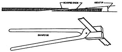
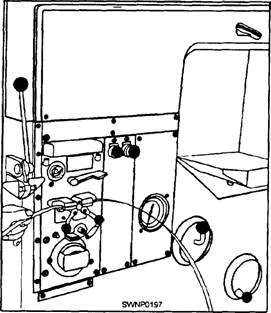
Figure 12-9.-14-inch band saw. Avoid twisting the blade by trying to turn sharp corners. Remember that you must saw around comers. If you want to saw a very small radius, use a narrow blade. If you find that a saw cut cannot be completed, it is better to saw out through the waste material to the edge of the stock than to back the blade out of the curved cut. This will prevent accidentally drawing the blade off the wheels. BAND SAW teeth are shaped like the teeth in a hand ripsaw, which means that their fronts are filed at 90 degrees to the line of the saw. Reconditioning procedures are the same as they are for a hand ripsaw, except that very narrow band saws with very small teeth must usually be set and sharpened by special machines. A broken band saw blade must be BRAZED when no accessory welder is available. The procedure for brazing is as follows: 1. SCARF the two ends to be joined with a file so that they may be joined in a SCARFJOINT(fig. 12-10). 2. Place the ends in a brazing clamp, or some similar device, that will permit them to be brought together in perfect alignments. 3. Coat the filed surfaces with soldering flux. 4. Cut a strip of silver solder the length of the scarf and the width of the blade. Coat it with flux and insert it between the filed surfaces. 5. Heat a pair of brazing tongs bright red and clamp the joint together. The red-hot tongs will heat the blade and melt the solder. Keep the tongs clamped on the joint until they turn black. 6. Smooth the joint on both sides with a flat file, and finish it with fine emery cloth. Figure 12-11 shows band ends being joined by using the butt welder-grinder unit. The entire procedure for joining is as follows: 1. Trim both ends of the band square; clean them thoroughly. Butt the ends together in the jaws of the welder-grinder unit; make sure that the ends are aligned and that the seam is centered between the welder jaws. First, set the resistance knob to agree with the dial for the width of band you are going to weld Then press and
Figure 12-10.-Rejoining a broken band saw blade.
Figure 12-11.-Butt welder-grinder unit. hold the WELD button until the blade ends fuse together. Let the weld cool for a few seconds and then press the ANNEAL button until the welded area heats to a dull cherry red. Hold the welded area at that temperature momentarily by jogging the button, and then allow the temperature to fall off slowly and gradually by increasing the time between jogs. (Allow about 10 seconds for this last phase.) 2. After the band has been annealed, take it out of the welder jaws and grind the weld bead with the small grinder. Grind the weld area to the same thickness as the rest of the band. Check the back edge of the band for burrs and misalignment; grind off irregularities. After the grinding is completed, place the band in the butt welder-grinder unit and reanneal the welded areas to destroy any hardness that may have developed. See the technical manual furnished with each machine. Causes of Blade Breakage A number of conditions may cause a band saw blade to break. Breakage is unavoidable when it is the result of the peculiar stresses to which such saws are subjected. The most common causes of blade breakage that may be avoided by good judgment on the part of the operator are as follows: (1) faulty alignment and adjustment of the guides, (2) forcing or twisting a wide blade around a curve of short radius, (3) feeding too fast, (4) dullness of the teeth or the absence of sufficient set, (5) excessive tension on the blade, (6) top guide set too high above the work being cut, and (7) using a blade with a lumping or improper] y finished braze or weld. When a saw blade breaks, shut off the power immediately, and then wait until the wheels stop turning before replacing the blade. Replacing Saw Blades To replace a bandsaw blade, open the wheel guard on each wheel. Raise the guide to the top position. Remove the throat plate from the table. Release the tension on the blade by turning the top wheel adjusting screw. Remove the blade and install the replacement. |
|
Privacy Statement - Press Release - Copyright Information. - Contact Us - Support Integrated Publishing |