Custom Search
|
|
  |
|
|
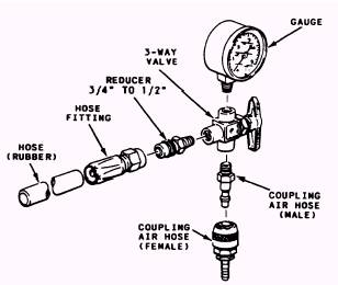
Before you attempt to perform a functional test, you should ensure that the work area surrounding the preserver is free of all foreign objects. This is done to prevent any accidental damage to the life preserver. When you perform a functional check, you want to ensure that the system operates as if the aircrew member were using it in an emergency. Therefore, your first step is to pull the actuation toggle. The preserver should fully inflate to its design shape without any evidence of restriction in less than 30 seconds. If the preserver does not meet this requirement, you will have to determine the reason and correct it. To do this, first look at your stem and valve. Sometimes dirt or foreign matter can cause a slow inflation. If you make any corrections, the preserver is functionally tested again. Deflate the preserver by using a vacuum pump and a 3/8- or 1/2-inch inside diameter rubber hose. Attach one end of the rubber hose to the vacuum pump, and the other end will go to the oral inflation valve or to the carbon dioxide cylinder valve, depending on which type you are using. After the preserver has been completely deflated, release the oral inflation valve or put the CO2 cylinder back into the valve. The functional check is only performed when the preserver is placed into service and every fourth calendar check after that. LEAKAGE TEST All life preservers are subjected to a leakage test each calendar/phase inspection. This test is performed each time the preserver comes into be checked, even when a functional test is required. A special test fixture is needed to perform this test. Test Fixture A suggested test fixture, consisting of a threeway valve, pressure gauge, and adapters for compartments being tested, is shown in figure 6-16. The fixture must be fabricated to meet the requirements of the schematic shown in figure 6-17.
Figure 6-16.-Leakage test fixture life preserver.
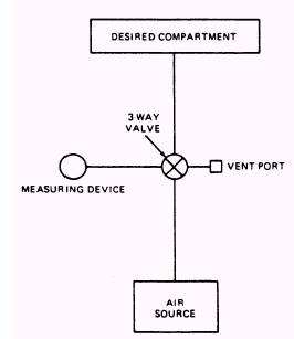
Figure 6-17.-Test rig schematic. Test Procedure To test life preservers, proceed as follows: 1. Ensure all carbon dioxide has been removed from any preserver that has been functionally tested. 2. To test the LPU-28/P life preserver, insert a 3/4-inch O.D. rubber hose into the oral inflation
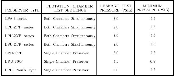
Table 6-7.-Life Preserver Test Pressures
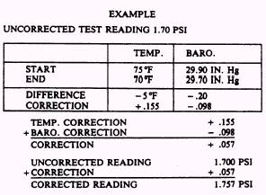
hose mouthpiece. Maintain pressure between the rubber hose and the oral inflation hose mouthpiece to ensure a good seal. Depress the valve on the oral inflation hose and alternately position the leakage test fixture valve between the measuring device, vent, and air supply until the overpressure relief valve opens (2.5 psig .5 psig). Rotate the leakage test fixture valve to the measuring device position to ensure that the life preserver is inflated to the proper pressure. Release the valve on the oral inflation hose. Inspect for proper operation of the relief valve. 3. To test all preserver chambers, except LPU-28/P, unlock the oral inflation valve and insert it into the rubber hose. Rotate the valve to the air supply position and inflate the chamber. Alternately position the valve between the measuring device, vent, and the air supply until the proper pressure is attained. 4. Turn off the air supply, and after a minimum of 15 minutes, readjust the pressure, if necessary, to the original pressure. Refer to table 6-7. 5. Disconnect the air supply and check test fixture for leaks. Ensure all valves are closed. 6. Record temperature and barometric pressure. 7. Four hours after the adjustment period in step 4, record the test pressure. 8. Record temperature and barometric pressure and correct test pressure for any changes in temperature and barometric pressure. Figure 6-18 is an example of how you would record this information.
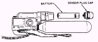
Figure 6-18.-Example for recording readings. CAUTION DO NOT SUBMERGE LPU-23/P SERIES AND LPU-24/P SERIES LIFE PRESERVERS IN WATER TO CHECK FOR LEAKS. After 4 hours, if the pressure of the chamber is below 1.60 psig, inflate to leakage test pressure and coat with a soap solution to locate any leaks. Mark any leak area you find. Rinse the preserver with fresh water, air dry it, and repair it in accordance with NAVAIR 13-1-6.1. If the preserver has held the required pressure, deflate it. Ensure that the inflation valve lever is cocked. Install a carbon dioxide cylinder. Battery Visual Inspection, LPU-23/P (Series) and LPU-24/P (Series) To inspect the batteries installed in the FLU-8A/P series inflator, proceed as follows: WARNING NO OBJECTS SHOULD BE INSERTED IN SENSOR PLUG SIDE PORTS FOR ANY REASON. With the aid of a standard 17/32-inch socket, remove the sensor plug cap. Remove the battery and check it for leakage and corrosion. Check the sensor plug cap for cracks. The battery has a twoletter code stamped on it that corresponds with the month and year of manufacture. The date of manufacture for the battery, PN 849AS 160, is displayed in the lot number stamped on the battery case. The battery has a total life of 4 years from the date of manufacture. Replace any battery if the total life of the battery expires prior to the next calendar inspection. Check this date of manufacture on each battery. Also check the date of installation recorded on the Aviation Crew Systems History Card. Reinstall or replace battery if needed. Ensure that the date of installation and date of manufacture are recorded on the Aviation Crew Systems History Card. See figure 6-20 for battery arrangement. Battery Voltage Testing, LPU-23/P (Series) and LPU-24/P (Series) Before installing any battery, you must be sure that it has enough energy to operate the FLU-8A/P inflator. A digital reading voltage multimeter must be used for this test.
Figure 6-20.-Battery arrangement.
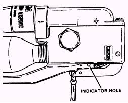
Figure 6-19.-Checking for silver indicator. This completes the testing for leaks within the flotation assembly. To complete the calendar inspection, you will have to inspect the remaining components of the life preserver. |
 
|