Custom Search
|
|
  |
|
|
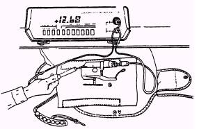
VISUAL INSPECTION The visual inspection is performed along with each calendar inspection, at which time it is performed before you perform the leakage test. To perform a visual inspection, inflate the preserver to 1 psi and look it over real good. Look for any fabric cuts, tears, deterioration, or abrasion. Any of these defects can cause leakage. Check the valve stem for security and ensure that the silver indicator is not visible in the firing check port (indicator hole) (LPU-23/P and LPU-24/P). See figure 6-19. If the silver indicator is visible, the inflator is spent and the automatic feature of the inflator is negated. A new inflator should be installed on the life preserver to replace the previously spent inflator. Refer to NAVAIR 13-1-6.1. LPU-23/P and LPU-24/P series preservers use the FLU-8A/P automatic inflator. The service life of each FLU-8A/P series automatic inflator is 66 months from the date of manufacture. If service life expires prior to the next scheduled calendar inspection, replace the inflator. Refer to NAVAIR 11-100-1, Cartridges and Cartridge Actuated Devices for Aircraft and Associated Equipment. Also refer to NAVAIR 13-1-6.2, section 2-5, Cartridges and Cartridge-Actuated Devices (General Safety Instructions). Do not use a needle voltage multimeter. The test leads of the multimeter should be provided with a standard test probe ( + ) and a banana type test plug (-). When using the multimeter, you should ensure that it is set in the voltage-measuring mode and NOT the resistance-measuring mode. A resistance measurement will trigger the squib and fire the inflator. Insert the negative (-) test probe into the end port of the sensor plug. Remove you hand. Faulty readings can be obtained or the squib may fire if the body becomes an electrical pathway between the sensor pin and any conductive part of the inflator assembly. Now, using the pointed positive (+) probe, touch and maintain contact with one of the screw heads near the lever end of the inflator. Refer to figure 6-21. Wait 15 seconds for the FLU-8A/P circuit to stabilize after connecting the test leads before taking the voltage reading. The voltage reading should begin at a high value and then gradually shift downward before final stabilization. If no downward shift in meter reading occurs, the FLU-8A/P inflator will be rejected. A reading of +12 volts or more indicates the battery is at full power and installed correctly. A reading of -12 volts or more indicates the battery is installed backwards. The battery must be reversed. A reading of zero volts indicates the battery contact is faulty or the battery is not installed properly. Inspect and correct if necessary. If a correct battery voltage reading cannot be obtained with a battery of verified full charge properly installed, the inflator is defective. Reject and report for an engineering investigation according to Volume III, OPNAV 4790.2.
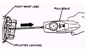
Figure 6-21.-Testing battery. Inspect life preserver inflation assemblies as follows: Remove the carbon dioxide cylinder from the valve assembly. Examine the inflation device, actuating lever and lanyard, and locking pins for fraying, corrosion, stripped threads, and other damage. If required, remove any sharp edges from the valve with a fine, round file. On LPU-28/P, LPU-30/P, and LPP life preservers, operate the toggle three or four times. Ensure that the lever moves freely and the piercing pin moves properly inside valve body. On life preservers with beaded inflation handles, operate beaded inflation handle three or four times. Ensure that the lever moves freely and the piercing pin moves properly inside valve body. Ensure that the packaging cord loop is not pinched between the piercing pin and the actuating lever. If there is free play in the actuating lever when it is in its cocked position, the packaging cord loop is pinched. If necessary, reinstall the cord. Refer to NAVAIR 13-1-6.1. NOTE: Each time the inflation assembly gaskets or the inflation assembly is removed and replaced for any reason, a functional test must be conducted. Use new gaskets when you replace the device. If any discrepancy is noted in the inflation device that is not repairable, remove the assembly and install a new inflation device. If carbon dioxide cylinder locking screws are installed on LPA type and LPU type life preservers, remove them. Ensure that CO2 cylinder locking screws are installed on LPU-30/P life preservers. Inflation Lanyard Pull Test Special Equipment Required Quantity Description Reference Number 1 Pull-Scale, DPP-50 0 to 50 lb or equivalent
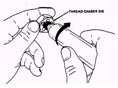
Figure 6-22.-Inflation lanyard pull test. To perform the inflation lanyard pull test, proceed as follows: 1. Ensure that the carbon dioxide cylinders have been removed. Actuate the inflation assembly. This test is testing the lanyard itself. It isn't designed to test the pull of the inflation assembly. 2. On life preservers with beaded inflation handles, attach a pull scale to top end (end opposite inflation lanyard) of beaded inflation handle (fig. 6-22). 3. On LPP and LPA-1/1A life preservers, attach the pull scale to the actuating lanyard at the binder knot immediately above the knob. 4. Exert a 25-pound straight pull on the inflation lanyard. Remove scale. 5. Examine the inflation lanyard for frays, ruptures, thin spots, split casing, and security of knots. 6. Replace any unsatisfactory inflation lanyards. Installation of Cylinders: LPA-1/1A (Series), LPA-2 (Series), LPU-21/P (Series), LPU-30/P, and LPP-1 (Series) Prior to installing any CO2 cylinder, it must be weighed and the threads cleaned. By using the cylinder thread chaser die, you turn the thread chaser to the full extent of the threads on the CO2 cylinder to cut free any excessive cadmium plating covering the threads (fig. 6-23). Weigh the charged cylinder and compare the stamped minimum weight with the scale weight. Discard and replace the cylinder if the scale weight is 2 grams less than stamped minimum weight. Loosen the inflator setscrew if it is installed and ensure that the inflator lever is in the cocked position. To assure a firm cylinder seat, conduct a cylinder thread count. The threaded portion of the cylinder neck must contain a minimum of seven full threads to assure a firm cylinder seat
Figure 6-23.-Cleaning threads. within the valve body. Any cylinder found with less than seven full threads must be discarded. CAUTION STEEL THREADS ON CARBON DIOX-IDE CYLINDERS CAN CAUSE DAM-AGE TO ALUMINUM THREADS ON INFLATORS IF THE CYLINDER IS NOT CAREFULLY THREADED. IF BINDING OCCURS DURING THREAD- ING, REPLACE THE CYLINDER. After performing a functional test, insert a new seat seal gasket from a kit. At intermediate inspection intervals, inspect the condition of the gasket and replace it if necessary. Install the CO2 cylinder into the inflator as far as hand twisting will permit. Tighten the setscrews, if installed. NOTE: When you replace the CO2 cylinder to the inflator, ensure that the CO2 cylinder passes through the holding patch loop. Do not install the setscrews in LPA-2 and LPU-21/P life preservers. For all other life preservers, a missing setscrew does not warrant removal of the preserver from service until a replacement setscrew can be obtained. Safety-wire the inflator as required. Installation of Cylinders, LPU-23/P (Series) and LPU-24/P (Series) To install cylinders, proceed as follows: Weigh a charged CO2 compare the stamped minimum weight with the scale cylinder and CO2 cylinder.
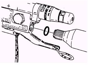
Figure 6-24.-Inserting new O-ring and CO weight. Discard and replace the cylinder if its scale weight is 2 grams less than its stamped minimum weight. By using the cylinder thread chaser die, figure 6-23, you turn the thread chaser to the full extent of the threads on the CO2 cylinder to cut free any excessive cadmium plating covering the threads. Insert new O-ring and turn the CO2 cylinder into inflator body as far as hand twisting permits. See figure 6-24. Battery Replacement, LPU-23/P (Series) and LPU-24/P (Series) To replace batteries, proceed as follows: Remove the sensor plug cap with a standard box wrench. WARNING BATTERIES MAY EXPLODE IF RE-CHARGED OR IF THEY ARE DIS-POSED OF IN A FIRE. Remove the old batteries and discard them. CAUTION NEVER REPLACE ONE BATTERY; ALWAYS REPLACE THE PAIR. Remember to record the date of manufacture and the date of installation of new batteries on the Aviation Crew Systems History Card. NOTE: Batteries have a total life of 2 years from the date of manufacture. Do not install batteries if their total life expires prior to the next scheduled calendar inspection. Install batteries in accordance with figure 6-20. WARNING ENSURE THAT THE SENSOR PLUG CAP IS TORQUED TO THE CORRECT VALUE. On FLU-8A/P only, torque the sensor plug cap to 5 in-lb using 17/32-inch socket and torque wrench. |
 
|