Custom Search
|
|
  |
|
|
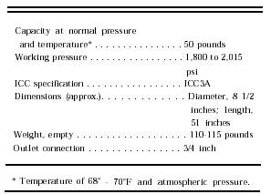
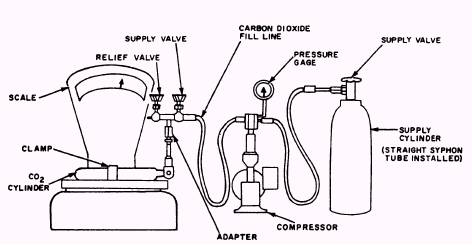
CO2 SUPPLY CYLINDERS Figure 8-2 illustrates the standard supply cylinder used universally in recharging various types of CO2 cylinders. A cutaway view of the cylinder valve is also shown. Table 8-1 lists some of the most pertinent data concerning supply cylinders. INSPECTING CO2 CYLINDERS AND RECHARGING Cylinders, including some of those of new manufacture, continue to bear ICC markings and, Table 8-1.-Specifications On Supply Cylinders
until amendment to Department of Transportation (DoT) regulations, such markings will remain in use. Compressed gas cylinders, including CO2 cylinders must not be refilled if the hydrostatic test date has expired. This date, expressed by month-year, e.g., 8-70, is stamped on the shoulder of the cylinder each time the cylinder is retested. The hydrostatic test date is considered as having expired if the latest date stamped on the cylinder precedes the current date by more than 5 years. Cylinders that do not exceed 2 inches in outside diameter and that are less than 2 feet long are exempt from the hydrostatic retest. The hydrostatic retest date applies to multiplace life raft cylinders; if the cylinder is due for a test, discharge and disconnect the cylinder. Obtain a new cylinder from supply as a replacement, and forward the old cylinder to an activity capable of conducting a hydrostatic test. Many nonshatterable cylinders are identified by the words NONSHATTERABLE, NON-SHAT, or SHATTERPROOF stamped (not stenciled) on the shoulder or side of the cylinder. Substitution of a "shatterable" for a "nonscatterable" cylinder is not authorized. Personnel who handle compressed gas cylinders must be familiar with the color coding of cylinders. Color coding is provided as a hazard warning, and should not be used by itself to identify the contents of a cylinder. In the event of conflict with other markings, or doubt as to the contents, the cylinder should be returned to the local supply activity, (non-RFI). All carbon dioxide inflation cylinders must be painted gray, and markings must be in black letters 1/4-inch high. The information must include gross weight, tare weight, weight of carbon dioxide, and date of latest recharge. Paint and stencil the cylinder as required, and ensure that all markings are included as necessary. Ensure that all carbon dioxide cylinders used for life raft inflation assemblies received from supply, except those used on the one-man rafts, have syphon tubes installed. Gently tap the inverted cylinder with a small piece of wood. If any rust or other contamination falls from the cylinder, reject that cylinder, and draw another cylinder from supply; repeat the contamination check. Replace the stem in the inflation assembly valve, install a new sealing washer, and thread the inflation assembly valve onto the cylinder and tighten. Inspection for deterioration of the cylinder will consist of a visual examination for the defects listed below. Cylinders with defects that approximate the physical dimensions indicated in the following list will be condemned and returned to supply. 1. Corrosion pits in a general corrosion area that exceed a depth of 1/32-inch, or isolated pits not in a general corrosion area that exceed a depth of 5/64-inch. 2. Dents that exceed a depth of 1/16-inch, or whose major diameter is more than 32 times the depth. 3. Cuts or gouges more than 1/16-inch, or whose major diameter is more than 32 times the depth. 4. Visible arc or torch burns. 5. Evidence that the cylinder has been in a fire. 6. Discernible bulges.
Figure 8-3.-CO2 recharging schematic. Now that you have inspected the CO2 cylinder, you are ready to recharge the bottle. Figure 8-3 shows a recharging setup. Notice in the figure that you need scales, a recharge pump, a supply cylinder, and the necessary lines and valves. Proceed as follows: 1. Place the CO2 cylinder on the scales. NOTE: An accurate scale with a capacity of 100 pounds is necessary. The scale should have 1/100 pound graduations. 2. Weigh and record tare weight (empty weight of cylinder, valve and cable assembly) of the inflation assembly. 3. Install proper charging adapter on the inflation assembly. 4. Secure the inflation assembly to the weighing pan located on the scales before applying any pressure to the cylinder being recharged. 5. Open the supply cylinder valve, fill line valve, and relief valve. This is done to purge (get the air out of) the complete line. Once the line is purged, close the fill line valve and the relief valve. You must be careful when purging the line; you are dealing with a high pressure. If you do not secure the fill line before you apply pressure, the line may start a whipping action and damage anything or anyone that it hits. 6. After purging the line, connect the fill line to the inflation assembly. Ensure that the line is free from contact with any objects along the entire distance from the compressor to the charging
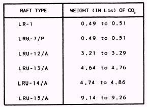
Table 8-2.-Carbon Dioxide Charge adapter. If the line does not hang free, accurate weight reading cannot be obtained. At this time, you must zero your scales. By zeroing the scales, you will be able to recharge the exact amount of CO2 into the inflation assembly. See table 8-2 for carbon dioxide charges. 7. Ensure that the inflation assembly valve is open. If it is closed, you cannot recharge the assembly. 8. Open the fill line valve slowly until you hear C O2 flowing through the line and into the inflation assembly, and the scale's indicator shows the recharging cylinder is gaining weight. 9. Allow carbon dioxide to cascade (flow freely) from the supply cylinder until the scales indicate that the cylinder being recharged isn't receiving anymore CO2. If you haven't reached the gross weight required (tare weight plus weight of charge) start the compressor and complete charging. Stop the compressor upon reaching the proper gross weight. At this time, you have completed the recharging process, and you must secure the equipment. 10. To shut the equipment down, start by securing the inflation assembly valve, and shut off the compressor. Then secure the fill line valve. Open the relief valve; this will relieve any pressure you may have in the line between the fill line valve and the inflation assembly. Disconnect the fill line from the inflation assembly and remove the charging adapter. To secure the rest of the system, all you have to do is close the supply cylinder valve and bleed the system by opening the fill line valve. If, during the recharging process, the cylinder being charged ceases to gain in weight, there may be one of two things wrong: 1. The supply cylinder may contain less than 10 pounds of carbon dioxide. In this case, a fully charged supply cylinder should be used and the partially charged cylinder reserved to start the recharging of an empty cylinder. 2. The connecting lines may have become stopped up with carbon dioxide snow. This may be caused by water in the supply cylinder or too small a valve passage (less than 1/8 in) in the supply cylinders. In this case, the disc assembly (disc-type valve) or the cylinder valve (seat-type valve) should be securely seated and the pump shut off. The connections should be broken and cleared of the carbon dioxide snow. The line will actually clear itself if allowed to stand for some length of time, but this can be hastened by applying a flame or torch to the tubing. The line should then be blown out with air to clear it of water or foreign matter. |
 
|