Custom Search
|
|
  |
|
|
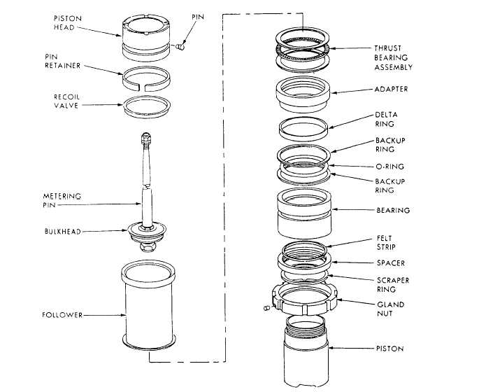
ALIGNMENT AND ADJUSTMENT Improper rigging or adjustment of landing gear linkages results in a significant number of unsafe or hung landing gear discrepancies. Most landing gear, when in an overcenter and locked position (up or down), requires very little interference or binding to prevent its initial movement.Alignment of newly installed landing gear assemblies or individual components should be in strict accordance with the procedures outlined in the applicable MIM. Complete assemblies are aligned in a specified sequence, with designated steps throughout the sequence that require quality assurance verification before proceeding to the next step. Landing gear doors may have to be deactivated or disconnected to check for proper up lock actuation and gear up clearances.Complete alignment includes down-and-locked adjustment, up-and-locked adjustment, and proper door operation. Verification of the emergency landing gear system operation is normally required in verifying the landing gear system. Some MIMs cover the emergency system as a separate procedure, but a complete operational checkout should include the emergency backup system.WARNING Ensure that all personnel involved in landing gear maintenance are clear of the landing gear and doors and that signals between the person in the cockpit and the crew leader are clearly understood before raising or lowering the landing gear. Failure to do so could result in personnel injury.RECOIL STRUT MAINTENANCE According to current maintenance directives, maintenance of recoil struts (including minor repair and miscellaneous parts replacement) should be confined to work that can be performed with only partial disassembly of the equipment. Instructions for major or complete overhaul are covered in overhaul instructions manuals for recoil struts, and such work is performed by specialized shops.LOWER STRUT AND GLAND SEAL REPLACEMENT On most aircraft the piston O-rings and delta rings can be replaced at the organizational level of maintenance while the strut is installed on the aircraft. Procedures for replacing the seals in a main gear recoil strut at the organizational level of maintenance consist of jacking the aircraft in accordance with the applicable MIM. Remove the wheel and brake assemblies so that handling of the lower strut is easier. Remove the cap from the strut filler valve and release the nitrogen pressure from the strut by opening the valve swivel nut counterclockwise. Remove the necessary wire bundles, hydraulic lines, etc., that form a connection between the upper cylinder and lower piston of the strut. Remove the up and down lines from the gear actuating cylinder. Connect a hand pump or check and fill stand lines so that the strut may be retracted to an angle that will allow the piston to be withdrawn from the cylinder. Cap any loose lines or fittings to prevent contamination. On some aircraft, you will have to use a spring compressor or some other means to release tension on the gear down lock mechanism so that the gear can be partially retracted.With the strut cylinder secured in the partially retracted position and all pressure released from the strut, the upper and lower torque arms can be disconnected. Cut the lockwire and remove the lock screws from the gland nut. Figure 12-17 shows a main gear recoil strut piston. Refer to figure 12-17 while you read the following seal replacement material.With the piston supported, the collar or gland nut is unscrewed and the piston withdrawn from the cylinder. Pour the hydraulic fluid into a suitable container, and place the piston/axle assembly in a clean work area. Inspect the hydraulic fluid for evidence of rubber or metal particles that might indicate wear conditions within the strut.Remove the pin retainer and three pins from the piston head; then remove the piston head and the recoil valve. On some aircraft the retaining pins are press fitted while on others they are screwed in. Remove the metering pin assembly, follower, thrust bearing assembly, adapter, delta ring, and other removable parts in the order in which they are installed on the piston assembly, as shown in figure 12-17.The cylinder walls, piston head, adapter, follower, and bearings should be inspected for excessive wear and sharp edges. Minor nicks, scratches, or sharp edges can be polished out with a crocus cloth (steel parts) or aluminum oxide abrasive cloth (aluminum parts).Coat all seals and backup rings with hydraulic fluid and install in the reverse order of the disassembly sequence. Ensure that the adapter, follower, and recoil valve are facing in the right direction on the piston assembly. Once the piston assembly is reassembled, quality assurance should check for proper reassembly before inserting it into the cylinder.The inner surface of the cylinder and the outer surface of the piston are coated with hydraulic fluid, and the piston is immediately installed in the cylinder. The gland nut is tightened and the lock screws installed and safety wired. The torque arms arc reconnected and the strut lowered to its normal extended position. All linkage, hydraulic lines, wire bundles, and the brake and wheel assemblies arc installed in the reverse order of their removal. The strut is serviced as required by the applicable MIM or maintenance requirements card. Proper servicing is very important. Not all struts are serviced in the standard manner. Consult the appropriate MIM to prevent improper servicing and subsequent landing gear or structural failure. All linkage on the lower strut that was disturbed must be lubricated, the brakes bled, and the brakes and the landing gear systems operationally tested.
Figure 12-17.-Main gear recoil strut piston. |
 
|
|
|