Custom Search
|
|
  |
|
|
SERVICING, BLEEDING, AND
INSPECTING
SHOCK STRUTS For efficient operation of shock struts, the proper fluid level and pneumatic pressure must be maintained. Before you check the fluid level, you should consult the aircraft MIM. Deflating a strut can be a dangerous operation unless the servicing personnel are thoroughly familiar with high-pressure air valves and observe all the necessary safety precautions. Servicing The high-pressure air valve shown in figure 12-18 is used on most naval aircraft. This air valve is used on struts, accumulators, and various other components that must be serviced with high-pressure air or nitrogen. The following procedures for deflating a typical shock strut, servicing with hydraulic fluid, and reinflating is for instructional purposes only. See figure 12-19. For specific aircraft consult the appropriate aircraft MIM. 1. Position the aircraft so that the shock struts are in the normal ground operating position. Ensure that personnel workstands, and other obstacles are clear of the aircraft. NOTE: Some aircraft must be placed on jacks with their struts completely extended for servicing. 2. Remove the cap from the air valve, as shown in view A of figure 12-19.
Figure 12-19.-Servicing a landing gear strut.
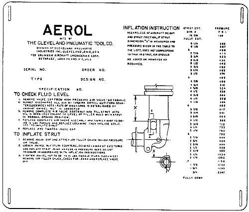
Figure 12-20.-Landing gear strut servicing instruction plate. 3. Release the air pressure in the strut by slowly turning the air valve swivel nut counterclockwise approximately 2 turns. This action can normally be accomplished with the use of a combination wrench. WARNING When loosening the swivel nut ensure that the 3/4-inch hex body nut is either lockwired in place or held tightly with a wrench. If the swivel nut is loosened before the air pressure has been released, serious injury may result to personnel. 4. Ensure that the shock strut compresses as the air or nitrogen pressure is released. In some cases, it may be necessary to rock the aircraft after deflating to ensure complete compressing of the strut. 5. When the strut is fully compressed, the air valve assembly may be removed by breaking the safety wire and turning the 3/4-inch body nut counter-clockwise. 6. Use the type of hydraulic fluid specified on the shock strut inspection plate to fill the strut to the level of the air valve opening. Figure 12-20 shows the instruction plate found on one type of aircraft main landing gear strut. NOTE: The instruction plate may be found on the strut or on the wheel door near the strut. Improper oil level in the strut chamber will decrease the shock absorbing capabilities of the strut and could cause the strut to bottom out during landing. This would damage the strut and/or wing structure. 7. Reinstall the air valve assembly, using a new O-ring packing. Torque the air valve body hex nut from 100 inch-pounds to 110 inch-pounds, as shown in view B of figure 12-19. 8. Lockwire the air valve assembly to the strut, using the holes provided in the body nut. 9. Inflate the strut, using a regulated high-pressure source of nitrogen or dry air. Under no circumstances should any type of bottle gas other than nitrogen or compressed air be used to inflate shock struts. The amount a strut is inflated depends upon the specific aircraft strut being serviced. One manufacturer may use a strut inflation chart, such as the one shown in view D of figure 12-19. The strut is measured as indicated at dimension "A." This measurement, in inches, is then located on the bottom of the inflation chart. For example, locate the measurement of 1.75 inches on the chart. From this point, vertically trace an imaginary line until it intersects the curved line. At this point of intersection, horizontally trace a second imaginary line to the left edge of the chart. The figure indicated at this point (550 psi) is the required pressure for that particular extension of the strut. All aircraft struts are not measured from the same points. View E of figure 12-19 shows another location where strut extension is measured. The proper procedure to use will always be found on the instruction plate attached to the shock strut. If these instructions are not legible, consult the applicable MIM. If the struts chamber is underpressurized, the strut may not overcome normal O-ring friction during extension on takeoff. This condition could prevent the strut from fully extending, thus the torque scissors limit switch would not actuate to close the electrical circuit to retract the gear. It would also cause the strut to bottom during taxiing and landing operations. If the struts chamber is overpressurized, the additional pressure will tend to keep the strut pressurized after takeoff. On those aircraft that use shrink mechanisms, the shrink mechanisms may be overloaded or stall the strut actuator as the gear retracts. If the gear retracts in the wing without shrinking, due to the failure of the shrink mechanism, damage to both the wing and landing gear may result. 10. Tighten the air valve swivel hex nut to a recommended torque of 50-70 inch-pounds. 11. Remove the high-pressure air-line chuck and install the valve cap fingertight Because some aircraft struts require special servicing procedures, the General Information and Servicing section of the applicable MIM should always be checked before servicing the shock struts of any aircraft. |
 
|
|
|
|
|
Integrated Publishing, Inc. - A (SDVOSB) Service Disabled Veteran Owned Small Business
|