Custom Search
|
|
  |
|
|
POWER BOOST BRAKE SYSTEM As a general rule, the power boost brake system is used on aircraft that land too fast to use the independent-type system, but are too light in weight to require the power brake control system. In this type of system, a line is tapped off from the main hydraulic system pressure line, but main hydraulic system pressure does not enter the brakes. Main system pressure is used only to assist pedal movement. This is accomplished through the use of power boost master cylinders. A schematic diagram of a typical power boost brake system is shown in figure 12-25. The normal system consists of a reservoir, two power boost master cylinders, two shuttle valves, and the brake assembly in each main landing wheel. A compressed air bottle with a gauge and release valve is installed for emergency operation of the brakes. In this system (fig. 12-25), main hydraulic system pressure is routed from the pressure manifold to the power boost master cylinders. When the brake pedals are depressed, fluid for actuating the brakes is routed from the power boost master cylinders through shuttle valves to the brakes.
Figure 12-25.--Power boost brake system. POWER BOOST BRAKE SYSTEM As a general rule, the power boost brake system is used on aircraft that land too fast to use the independent-type system, but are too light in weight to require the power brake control system. In this type of system, a line is tapped off from the main hydraulic system pressure line, but main hydraulic system pressure does not enter the brakes. Main system pressure is used only to assist pedal movement. This is accomplished through the use of power boost master cylinders. A schematic diagram of a typical power boost brake system is shown in figure 12-25. The normal system consists of a reservoir, two power boost master cylinders, two shuttle valves, and the brake assembly in each main landing wheel. A compressed air bottle with a gauge and release valve is installed for emergency operation of the brakes. In this system (fig. 12-25), main hydraulic system pressure is routed from the pressure manifold to the power boost master cylinders. When the brake pedals are depressed, fluid for actuating the brakes is routed from the power boost master cylinders through shuttle valves to the brakes.
Figure 12-27.-Power brake control valve (pressure ball check type). is a check valve, which prevents loss of brake system pressure in case of main system failure. The next unit is the accumulator, the main purpose of which is to store a reserve supply of fluid under pressure. When the brakes are applied and pressure drops in the accumulator, more fluid enters from the main system and is trapped by the check valve. The accumulator also acts as a surge chamber for excessive loads imposed upon the brake hydraulic system. Following the accumulator are the pilots and copilots brake valves. The purpose of a brake valve is to regulate and control the volume and pressure of the fluid that actuates the brake. Four check valves and two one-way restrictors, sometimes referred to as orifice check valves, are installed in the pilots and copilots brake actuating lines. The check valves allow the flow of fluid in one direction only. The orifice check valves allow unrestricted flow of fluid in one direction, from the pilots brake valve; flow in the opposite direction is restricted by an orifice in the poppet. The purpose of the orifice check valves is to help prevent chatter. The next unit in the brake actuating lines is the pressure relief valve. In this particular system, the pressure relief valve is preset to open at 825 psi to discharge fluid into the return line. The valve closes at 760 psi minimum. Each brake actuating line incorporates a shuttle valve for the purpose of isolating the emergency brake
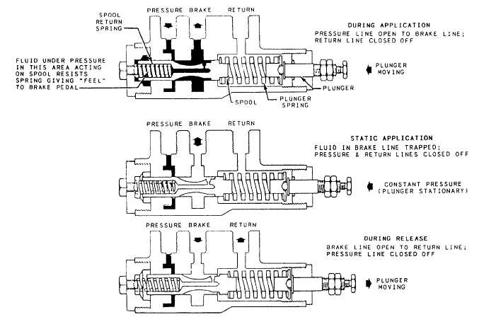
Figure12-28.-Power brake control valve (sliding spool type). system from the normal brake system. When brake actuating pressure enters the shuttle valve, the shuttle is automatically moved to the opposite end of the valve. This action closes off the inoperative brake system actuating line. Fluid returning from the brakes travels back into the system to which the shuttle was last open. |
 
|
|
|
|
|
Integrated Publishing, Inc. - A (SDVOSB) Service Disabled Veteran Owned Small Business
|