Custom Search
|
|
  |
|
|
Power Brake Control Valve
(Pressure
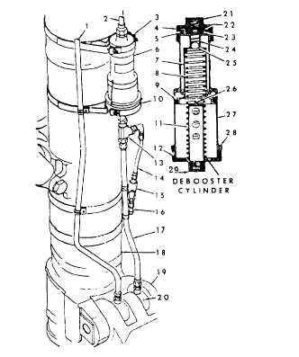
Ball Check Type) A power brake control valve of the pressure ball check type is shown in figure 12-27. The valve is designed to release and regulate main system pressure to the brakes and to relieve thermal expansion when the brakes are not being used. The main parts of the valve are the housing, piston assembly, and tuning fork. The housing contains three chambers and three ports. They are the pressure inlet, brake, and return ports.The piston assembly is made up of a piston head, piston shaft, pilot pin, and cross pin. The piston head separates the brake and return chambers. A cup seal prevents fluid from escaping to the return chamber when the brakes are applied. The seal is held in place by a retainer and piston return spring. The piston head has a hole drilled through its center for the flow of fluid to the return port. This hole is opened and closed by the pilot pin. The pilot pin also opens the pressure port. The flange of the pilot pin and the hole in the piston head are lapped together. The piston shaft connects the piston head with the tuning fork. The shaft is slotted, and the cross pin prevents it from turning.The tuning fork connects the brake pedal linkage with the control valve. It swivels on the housing and limits the maximum pressure directed to the brake. The upper arm of the tuning fork is a bar spring that bends from the point of the fulcrum when hydraulic pressure overcomes toe force.Power Brake Control Valve (Sliding Spool Type) A sliding spool-type power brake control valve is shown in figure 12-28. This valve consists basically of a sleeve and a spool installed in a housing. The spool moves inside the sleeve, opening or closing either the pressure or return port of the brake line. Two springs are provided. The large spring, referred to in the illustration as the plunger spring, provides "feel" to the brake pedal. The small spring returns the spool to the OFF position. When the plunger is depressed, the large spring moves the spool, which closes off the return port and opens the pressure port to the brake line. When the pressure enters the valve, fluid flows to the opposite end of the spool through a hole. The pressure pushes the spool back far enough toward the large spring to close the pressure port, but not open the return port. The valve is then in the static condition. This movement partially compresses the large spring, giving "feel" to the brake pedal. When the brake pedal is released, the small spring moves the spool back, opening the return port. This action allows fluid pressure in the brake line to flow out through the return port.Maintenance of the sliding spool brake control valve is limited to checking the action of the plunger. This is done by manually depressing the plunger until it bottoms, and then releasing it suddenly. If the plunger remains depressed (does not snap out), the valve is binding at the spool and sleeve. If binding occurs, the valve should be replaced. Disassembly of the valve is not permitted at the organizational level of maintenance, but may be performed by an intermediate or higher level activity.Brake Debooster Cylinder In some power brake control valve systems, debooster cylinders are used in conjunction with the power brake control valves. These units are generally used on aircraft equipped with a high-pressure hydraulic system and low-pressure brakes. The purpose of the brake debooster cylinder is to reduce the pressure to the brake and increase the volume of fluid flow. Figure 12-29 shows a typical debooster cylinder installation. The unit is being mounted on the landing gear shock strut in the line between the control valve and the brake. The schematic diagram in the illustration shows the internal parts of the cylinder.When the brake is applied, fluid under pressure enters the inlet port to act on the small end of the piston. The ball check prevents the fluid from passing through the shaft. Force is transmitted through the small end of the piston to the large end of the piston. As the piston moves downward in the housing, a new flow of fluid is created from the large end of the housing through the outlet port to the brake. Because the force from the small piston head is distributed over the greater area of the
1. Emergency system pressure line2. Main brake pressure line 3. Upper support clamp 4. Packing 5. Packing 6. Debooster cylinder assembly 7. Piston 8. Piston return spring 9. Packing 10. Lower support clamp 11. Riser tube 12. Packing 13. Tee fitting 14. Brake line (to pressure relief valve) 15. Brake pressure-relief valve 16. Overflow line 17. Brake tine (debooster to shuttle valve) 18. Shock strut 19. Torque link 20. Brake shuttle valve 21. Inlet port 22. Snapring 23. Spring retainer 24. Valve spring 25. Ball 26. Ball pedestal 27. Barrel 28. Lower cud cap 29. Outlet port Figure 12-29.-Brake debooster cylinder. large piston head, pressure at the outlet poet is reduced. At the same time, a greater volume of fluid is displaced by the large piston head than that used to move the small piston head.Normally, the brake will be fully applied before the piston has reached the lower end of its travel. However, if the piston fails to meet sufficient resistance to stop it (due to a loss of fluid from the brake unit or connecting lines), the piston will continue to move downward until the riser unseats the ball check valve in the hollow shaft. With the ball check valve unseated, fluid from the power control valve will pass through the piston shaft to
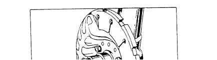
Figure 12-30.-Typical single disc brake installation. replace the lost fluid. Since the fluid passing through the piston shaft acts on the large piston head, the piston will move up, allowing the ball check valve to seat when pressure in the brake assembly becomes normal. When the brake pedal is released, pressure is removed from the inlet port, and the piston return spring moves the piston rapidly back to the top of the debooster. This rapid movement causes a suction in the line to the brake assembly, resulting in faster release of the brake. |
|
|
|