Custom Search
|
|
  |
|
|
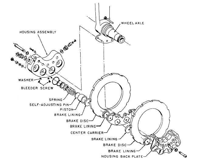
EMERGENCY BRAKE SYSTEM On all aircraft except those equipped with independent-type brake systems, an emergency brake system is provided. On some aircraft a pneumatically operated emergency system is provided. Others have a reserve hydraulic system; an emergency hydraulic reservoir retains a sufficient supply of hydraulic fluid for manual operation of the brakes in case no hydraulic power is available. The power boost brake system, described earlier, is equipped with a pneumatically operated emergency system. The emergency system consists of a T-handle, compressed air bottle, air release valve, and pressure gauge. The system is operated by pulling the T-handle. This releases the compressed air stored in the air bottle. Air pressure unseats the shuttle valves at the air inlet ports and seats the hydraulic pressure ports. Air pressure is then applied directly to the brakes. Once air pressure has been applied, the brake can be released only by depressing a button on the air release valve. Brake systems must be bled after using the emergency pneumatic systems, and the air storage bottle must be serviced with the specified amount of dry compressed air or nitrogen. A pressure gauge indicates the amount of air in the bottle, in pounds per square inch (psi). BRAKE ASSEMBLIES Learning Objective: ldentify the various types of brake assemblies. Brake assemblies commonly used on naval aircraft are the single disc, dual disc, multiple or trimetallic disc, and segmented rotor. The single and dual disc types are more commonly used on small aircraft; the multiple or trimetallic disc types are normally used on medium sized aircraft; and the segmented rotor types are commonly found on heavier types of aircraft. SINGLE DISC BRAKES The single disc brake is very effective for use on smaller types of aircraft. Braking is accomplished by applying friction to both sides of a rotating disc-the disc being keyed to the landing gear wheel. There are several variations of the single disc brake; however, all operate on the same principle and differ mainly in the number of cylinders and the types of brake housing. Brake housings may be either the one piece or divided type. Figure 12-30 shows a single disc brake installed on an aircraft, with the wheel removed. The brake housing is attached to the landing gear axle flange with mounting bolts.
1. Brake disc Figure 12-31.-Exploded view of single disc brake assembly. Figure 12-31 shows an exploded view of a typical single disc brake assembly. This brake assembly has a three-cylinder, one-piece housing. Each cylinder in the housing contains a piston, a return spring, and an automatic adjusting pin. There are six brake linings (pucks), three on the inboard side of the rotating disc and three on the outboard side of the rotating disc. These brake linings are often referred to as "pucks." The outboard lining pucks are attached to the three pistons, and they move in and out of the three cylinders when the brakes are operated. The inboard lining pucks are mounted in recesses in the brake housing and are stationary. Hydraulic pressure from the brake control unit enters the brake cylinders and forces the pistons and their pucks against the rotating disc. At the same time, the piston pushes against the adjusting pin (through the spring guide) and moves the pin inboard against the friction of the adjusting pin grip. The rotating disc is keyed to the landing gear wheel so that it is free to move laterally within the brake cavity of the wheel. Thus, the rotating disc is forced into contact with the inboard pucks mounted in the housing. This lateral movement of the rotating disc ensures equal braking action on both sides of the disc. When pressure is relieved, the force of the return spring is sufficient to move the piston away from the brake disc, but it is not enough to move the adjusting pin, which is held by the friction of the pin grip. The piston moves away from the disc until it stops against the head of the adjusting pin, which provides a preset clearance between the pucks and the disc. The self-adjusting feature of the brake will maintain the desired puck-to-disc clearance, regardless of lining wear. Thus, regardless of the amount of wear, the same travel of the piston will be required to apply the brake. Maintenance of the single disc brake may include bleeding, performing operational checks, checking
Figure 12-32.-Dual disc brake. lining wear, checking disc wear, and replacing worn linings and discs. A bleeder valve is provided on the brake housing (fig. 12-31) for bleeding the single disc brake. Bleeding should be performed according to the instructions contained in the aircraft MIM. Operational checks are made during taxiing. Braking action for each main landing gear wheel should be equal, with equal application of pedal pressure and without any evidence of soft or spongy action. When pedal pressure is released, the brakes shouId release without any evidence of drag. All disc-type brakes must be checked periodically for lining wear. Excessively worn linings must be replaced. Lining wear may be checked by two methods. The method used depends upon the model of the brake assembly. Both methods are described later in this chapter. Before checking the brakes on any aircraft, always refer to the applicable MIM and use the method recommended by the aircraft manufacturer. |
 
|
|
|
|
|
Integrated Publishing, Inc. - A (SDVOSB) Service Disabled Veteran Owned Small Business
|