Custom Search
|
|
  |
|
|
INDEPENDENT-TYPE BRAKE SYSTEM The depth of independent brake system mainte-nance allowable at the intermediate and organizational levels of maintenance varies with the complexity of the components. System maintenance at the organizational level generally consists of servicing, troubleshooting, parts replacement, and "on aircraft" repairs. Bleeding of the brake system is discussed later in this chapter. Reservoir maintenance is limited to servicing, removal, repair, parts replacement, testing, and installation. Servicing of the reservoir requires that filtered hydraulic fluid be gravity fed into the reservoir through the filler opening until the sight gauge indicates it is full. The reservoir should not be overfilled. The area around the filler neck should be cleaned before you remove the filler plug to prevent any form of contamination from being introduced into the reservoir and the brake system. Maintenance of the reservoir, the master brake cylinder, and the brake assembly is discussed later in this chapter. As with other systems, a troubleshooting chart is furnished in the MIM for use in troubleshooting/ analyzing main landing gear wheel and independent brake system malfunctions. Chapter 3 of this training manual contains examples of troubleshooting tables and charts. POWER-TYPE BRAKE SYSTEM Organizational maintenance of the power/manual brake system consists of checking system operation, system adjustment, isolating malfunctions, and replacement and adjustment of system components. See figure 12-35. The checkout procedures in most MIMs are provided for use during established inspections or for use in performing trouble analysis. GENERAL BRAKE SYSTEM MAINTENANCE Proper functioning of the brake system is of the utmost importance. Inspections must be performed at frequent intervals, and maintenance work must be performed promptly and carefully. Prepare the aircraft for an operational checkout by installing the landing gear down locks, jacking the aircraft to provide proper ground clearance for the landing gear, and applying external electrical power. Placing the antiskid switch in the OFF position should illuminate the antiskid warning light. When the landing gear handle is moved to the UP position, the antiskid light should go out. At this point, external hydraulic power is slowly applied to the utility system. The wheels should not rotate. By placing the landing gear handle to the DOWN position, it should illuminate the antiskid light and free the wheels to rotate. The brake pedals should be fully depressed to apply the brakes a minimum of three times. With external hydraulic and electrical power removed from the aircraft, operationally check the emergency system by pulling the emergency brake handle. The wheels should not rotate when the handle is pulled. Releasing the handle should immediately release the brakes. If any portion of the operational or functional test does not meet the results specified in the MIMs, refer to the trouble analysis sheets for the brake system. Functional Tests Prepare the aircraft for a complete functional checkout by installing the landing gear down locks, jacking the aircraft to provide ground clearance for the landing gear, installing pressure gauges in the wheel brake assembl ys bleed ports, and applying external electrical and hydraulic power. When the antiskid switch is in the OFF position, the antiskid warning light will illuminate. Move the landing gear handle to the UP position, which will cause the antiskid warning light to go out. The gauges on the brake assemblies should indicate 650 to 1,000 psi. Place the landing gear handle to the DOWN position to illuminate the antiskid warning light. The brake gauges should indicate a maximum of 75 psi, and the wheels should be free to rotate. Remove electrical power from the aircraft. Depress the brake pedals several times to check braking action. Place a bubble protractor on the brake pedals and adjust to zero when the brakes are in the OFF position. When the brakes are fully depressed, the protractor should indicate 30 degrees 1 degree, and the hydraulic gauges on the brake assemblies should indicate the same pressure as the external hydraulic power source. The external hydraulic power is shut down and system pressure is relieved by operating the rudder pedals. Check brake accumulator action by fully depressing the brake pedals several times and checking the brake assembly action. Check the emergency brake system in the same manner as described for the operational checkout.
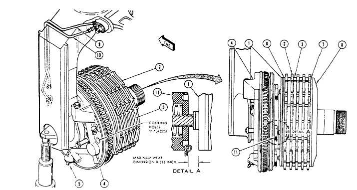
1. Primary disc assembly Figure 1236.-Wheel brake. The next steps of the fictional checkout require that the wheel and tire assemblies be removed and hydraulic power reapplied. Depress the brake pedals for approximately 1 minute, and check each power plate for hydraulic leakage. Check lining wear by depressing the brake pedals. Measure the gap between the face of the primary disc assembly (1) and the screw thread insert (11). See figure 12-36. Lining wear should not exceed 0.816 inch. Check running clearance by first applying the brake pedals until 1,200 psi is indicated on the gauges installed in the brake bleed ports. Measure the distance between the primary disc and the face of the screw thread insert. Release the brakes and measure the distance again. Subtract this dimension from that obtained with the brakes applied to obtain the running clearance. Clearance should be 0.070 to 0.119 inch. |
 
|
|
|
|
|
Integrated Publishing, Inc. - A (SDVOSB) Service Disabled Veteran Owned Small Business
|