Custom Search
|
|
  |
|
|
Repair and Replacement Polish minor nicks and scratches on metal parts with crocus cloth (Federal Specification P-C-458C for steel parts and P-C-451B for aluminum parts). During polishing, make sure that all dimensions are maintained within the specified limits and that seating and sealing surfaces are not damaged. Repair damage to anodized finishes on aluminum parts by applying a protective chemical film per Specification MIL-C-81706, class 1A, Form III. WARNING Chemical film materials are strongly oxidizing and are a fire hazard when in contact with organic materials such as paint thinners. Do not store or mix surface treatment materials in containers previously containing flammable products. Rags contaminated with chemical film material should be thoroughly rinsed and disposed of as soon as practical. When you replace a suspension bearing, stake the new bearing at the original stake points on both sides of the body by using a 3/16-inch-diameter ball in the staking tool. Verify the security of the bearing, and inspect the area around the staking indentations for possible fractures. Many parts for the repair of the Gladden master brake cylinder are provided in cure-date and overhaul kits. Replace all other worn or damaged parts that cannot be reworked to meet inspection requirements. Detail parts not provided in the kit maybe available from bulk stock. Lubrication Apply a light coat of hydraulic fluid to all sealing devices to aid in reassembly. The recommended lubricant for the suspension rod end bearing is grease, Specification MIL-G-23827. Reassembly Reassemble all interred parts in reverse order of disassembly by using an arbor press, or equivalent, and an AN350-4 nut to aid in assembly and to eliminate the possibility of personnel injury because of preload of springs. Testing The test equipment required includes a conventional hydraulic test bench capable of delivering fluid to 4,500-psi pressure at room temperature, plus the equipment illustrated in figures 12-43 and 12-44. The nominal extended length of the unit from the center of the end bearing to the end of the actuating rod is 15.31 inches. To proof test the inlet chamber and perform a leakage test, first apply 5 psi, and then 200 psi at the reservoir port with the brake port plugged. There
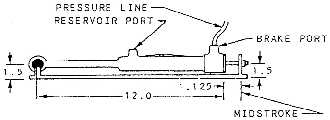
Figure 1243.-Piston, valve, and brake chamber proof test setup diagram.
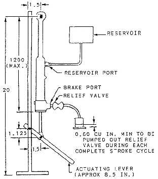
Figure 12-44.-Rod packing, cylinder leakage, and pumping function test. should be no external leakage for 1 minute from either port. To perform the piston, valve, and brake chamber proof test, install the unit in the jig (fig. 12-43), and harness it at the midstroke position with 25-psi hydraulic pressure applied at the brake port. There should be no external leakage. Leakage at the reservoir port should not exceed 1 drop per minute for 2 minutes after a 1-minute waiting period. If the unit tests satisfactorily at this stage, the pressure should be increased to 2,000 psi. There should be no external leakage, and leakage at the reservoir port should not exceed 1 drop per minute for 2 minutes after a 1-minute waiting period. When the foregoing test is completed, the unit is ready to receive a rod packing, cycling leakage, and pumping function test. With the unit extended and installed in the actuating fixture, a reservoir should be connected to the reservoir port and a 200- to 400- psi relief valve should be connected to the brake port. See figure 12-44. Operation of the manual lever through five full strokes should pump hydraulic fluid through the relief valve. Leakage at the piston rod gland should not exceed 1 drop at this time. Not less than 0.75 cubic inch of fluid should flow from the relief valve during anyone complete stroke cycle of the manual lever. There should be no evidence of binding at any time during these tests. BRAKE SHUTTLE VALVE Shuttle valve maintenance is generally limited to repairing leakage. External leakage may usually be repaired by tightening the end caps. If this does not stop the leakage, the end cap O-ring should be replaced. Internal leakage can usually be repaired by removing and flushing the unit with clean, hydraulic fluid. Excessive heating is a good indication of internal leakage through a shuttle valve. Excessive cycling of the emergency system pump is also an indication of a leaky shuttle valve. After an emergency system has been operated, all emergency system pressure should be bled off as soon as possible and the normal system restored to operation. |
 
|
|
|
|
|
Integrated Publishing, Inc. - A (SDVOSB) Service Disabled Veteran Owned Small Business
|