Custom Search
|
|
  |
|
|
AUTOMATIC BRAKE ADJUSTER VALVE Tests are not required on the individual adjuster valve parts. After disassembly, cleaning, inspection, repair or parts replacement, and complete reassembly have been accomplished, perform a bench test to determine whether the brake adjuster valve satisfies the required minimum specifications.Disassembly The brake adjuster valve should be disassembled in accordance with instructions contained in the MIM and/or 03 manual. Check the safety wiring before disassembly to expedite rewiring after reassembly.Cleaning Clean all parts except the nylon insert and O-rings with P-D-680 cleaning solvent. The insert and O-rings will normally be replaced upon each disassembly of the valve. Dry parts with dry, clean, filtered, compressed air.WARNING Do not inhale solvent vapors or direct compressed air against the skin. Failure to observe proper safety precautions could result in injury to personnel.Inspection Perform inspections under a strong light and with magnification. Inspect all threads for crossed, filled, or stripped conditions. Inspect all parts for nicks, scratches, scoring, corrosion, or other damage. Check all drilled passages for obstructions.Repair or Parts Replacement Replace any part that is damaged or does not function properly. During replacement and before actual reassembly, lightly coat all parts with hydraulic preservative fluid; assemble parts while they are wet.Reassembly Reassembly is essentially the reverse of dis-assembly. Directions for reassembly are provided in the MIM and/or 03 manual.Bench Test The bench test consists of a series of testsproof pressure, thermal crack, shuttle valve opening operation, shuttle valve closing operation, and leakage. Perform these tests in the order listed on a test bench, and not while they are installed in the aircraft. The test bench used must be capable of supplying hydraulic fluid filtered through a 3-micron filter at a maximum pressure of 2,250 psi. Conduct the tests at a room temperature of 70 to 90F and a fluid temperature of 70 to 110F. Before you start the test, bleed all air from the unit. After completing the test, remove the valve from the bench.Flush with hydraulic preservative fluid, drip-drain, and plug the ports. The cure date of the oldest scaling device should be rubber-stumped on the body of the valve, and the unit togged with the date and results of the test.To perform the proof pressure test, apply a hydro-static proof pressure of 2,250 psi to the RET (return) port with the BRAKE and PMV (power/manual valve) ports interconnected. Apply this pressure twice and hold for a 2-minute period each time. There should be no evidence of external leakage, failure, distortion, or permanent set. Perform the thermal crack test by applying pressure gradually to the BRAKE port with the RET and PMV ports open until the valve cracks. The residual pressure should not be less than 27 psi. Again, gradually increase pressure at the BRAKE port until the valve cracks. The cracking pressure should be between 30 and 37 psi. There should be no leakage from the PMV port.NOTE: During piston travel a volume of fluid will be displaced through the PMV port. Only the portion of displaced fluid that exceeds 10 cubic centimeters should be considered as leakage. No RET port fluid displacement should be considered leakage.
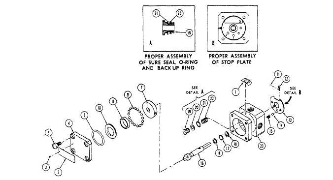
1. Decal Figure 1245.-Brake selector valve-exploded view. This procedure completes the thermal crack test. In preparation for the shuttle valve opening operation test that follows, block residual pressure in the BRAKE port using a pressure gauge as the plug.With the RET port open and BRAKE port capped, apply hand-pumped hydraulic pressure gradually to the PMV port. There should be a simultaneous increase of BRAKE port pressure with PMV port pressure. At a pressure of 60 to 80 psi in the PMV port, pressure in the PMV port and BRAKE port should become equal. A gradual increase in PMV port pressure to 1,500 psi should result in a proportionate increase in the BRAKE port pressure. Any displacement at the RET port should not be considered leakage during this phase of the bench test. The shuttle valve closing operation test begins with 1,500 psi from the previous phase still applied to the PMV port. Reduce the pressure at the PMV port to 150 psi, and then rapidly to 0 psi. The closing operation is evidenced by the venting of hydraulic fluid from the RET port as PMV pressure decreases from 20 psi to 0 psi. The final phase of the bench test is the test for leakage. This phase is started with 27-psi hydraulic pressure trapped in the BRAKE port. There should be no evidence of pressure decrease when it is measured over a period of 3 minutes. Continue the test with the BRAKE port capped and the RET port of the valve in an upright position. Fill the RET port cavity and a leakage measuring device with hydraulic fluid. Apply hand-pumped hydraulic pressure of 30 to 37 psi to the PMV port. Leakage at the RET port must not exceed 0.5 cubic centimeter per minute. Immediately after application of pressure, measure the leakage for a 3-minute period. Disregard volume displacement because of shuttle valve transition if leakage is not in excess of 0.5 cubic centimeter per minute. Increase the pressure to 125 psi and maintain for a 3-minute period. There should be no evidence of leakage. Further increase the pressure to 1,500 psi and maintain for another 3-minute period. There should be no leakage. |
|
|
|