Custom Search
|
|
  |
|
|
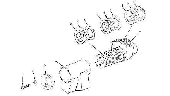
BRAKE SELECTOR VALVE Repair of the brake selector valve at the intermediate level of maintenance is limited to the replacement of cure-date items and parts listed under Spares and Replacement Parts Data in the "Intermediate Maintenance" section of the MIM.Figure 12-45 shows an exploded view of the selector valve. Observe the arrangement in which the
1. Screw Figure 1246.-Brake swivel. machine screws are lockwired to aid in reassembly. Disassemble the valve and clean all parts with P-D-680 cleaning solvent. Dry all parts thoroughly, using low-pressure, moisture-free, compressed air or a lint-free, clean cloth. Inspect all parts for scratches, cracks, scoring, burrs, nicks, excessive wear, and distortion. If any part other than those listed in the Spare and Repair Parts Data is faulty, the component must be tagged to show the fault and forwarded to the next higher level of maintenance.Replace all sealing devices and worn or damaged parts. Apply a light coating of hydrauIic fluid on all O-rings, backup rings, seals, and wear surfaces before reassembly. Note the proper assembly of the seal, O-ring and backup ring, and the proper assembly of the stop plate, as shown in figure 12-45. Reassembly is essentially the reverse order of disassembly. Steps that require quality assurance verification in the MIMs are identified by the letters "QA" after the applicable steps.When QA is assigned to a step or a heading that is immediately followed by substeps, the inspection is applicable to all substeps. The four machine screws that hold the selector valve assembly together must be tightened and properly lockwired.NOTE: In some MIMs, the steps in a procedure that require a QA inspection are underlined or italicized.Bench test the repaired valve to verify its ready-for- issue (RFI) condition. The hydraulic fluid used to test the valve must be continuously filtered by a 3-micron absolute, nonbypass filter upstream of the valve. Allow the test stand fluid to reach an operating temperature of 70 to 110F before the testing begins. The valve must pass a proof test, static pressure test, actuation (operational) test, and leakage tests. During the actuation test, the amount of torque required to operate the valve to any position should not exceed 40 inch-pounds with 3,000 psi applied to the pressure port. The requirements for each test are specified in the "Intermediate Repair" section of the MIM. |
 
|
|
|