Custom Search
|
|
  |
|
|
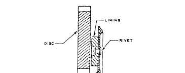
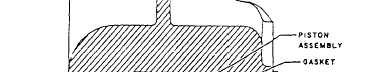
BRAKE ASSEMBLY MAINTENANCE Learning Objective: Identify the maintenance procedures for the single disc, the dual disc, and the bimetallic disc brake assemblies.The description and operation of the single disc, dual disc, multiple disc, and segmented rotor brake assemblies were covered earlier in this chapter. Additional maintenance information on the single and dual disc brake assemblies and a description and operation of the trimetallic disc brake assemblies are covered in this section.SINGLE AND DUAL DISC BRAKES Automatically adjusted single and dual disc brakes are designed to provide a satisfactory running clearance between the brake disc and the brake linings. The self-adjusting feature of the brake maintains the desired lining and puck-to-disc clearance, regardless of lining or puck wear. See figure 12-47. When you apply the brakes, hydraulic pressure moves each piston and its pucks or linings against the disc or discs as applicable. As the linings wear, the piston pushes against the adjusting pin (through the spring guide) and moves the pin against the friction of the adjusting pin grip. When you release the brake pressure, the force of the return spring moves the piston away from the brake disc, but it does not move the adjusting pin, which is held by the friction of the pin grip. The piston moves away from the disc until it stops against the head of the adjusting pin. Thus, regardless of the amount of wear, the same travel of the piston will be required to apply the brake, and the running clearance will be maintained.
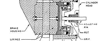
Figure 1248.-Cross-sectional view of a single disc brake assembly with captured torquing-type automatic adjuster.The automatic adjusting feature may be referred to as a captured torquing type or captured nontorquing type. Figure 12-48 shows a typical captured torquing-type automatic adjuster. It is mandatory that clearance be established between the linings and the discs before torquing the automatic adjusting nut to the amount specified for the brake involved. Otherwise, the brake will drag until an amount equal to the built-in
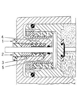
1. Locknut Figure 12-49.-Captured nontorquing-type automatic adjuster. clearance is worn from the face of the linings. With the adjusting nuts properly torqued, the friction between the grip and the adjusting pin is great enough to overcome the compression of the return spring, and the adjusting pin will be pulled through the grip only to compensate for lining wear. After torquing the automatic adjusting nuts to the specified value, back them off and retorque several times. This procedure will ensure proper mating of all parts and the correct torque on the final assembly. Figure 12-49 shows the captured nontorquing-type automatic adjuster used on some single and dual disc brake assemblies. Brakes that contain nontorquing adjusters can be identified by the locknut and threaded bushing over each adjusting pin. The only difference between the torquing-and nontorquing-type automatic adjustment is the method used to restrict the movement of the adjusting pin. The torquing-type adjustment uses a tapered grip, and the nontorquing uses one or more l/4-inch-wide grips composed of brass liners.
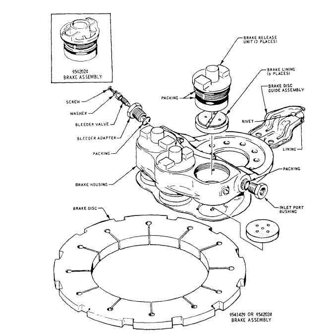
Figure 1250-Single disc brake-repair and parts replacement diagram. Spare grips are shipped with pilot pins installed to open the grip to the approximate diameter of the adjusting pin, thus preventing damage to the grjp during installation. The pilot pin is expelled as the grip is forced over the adjusting pin. If grips are to be reused when a brake is disassembled, they should have the pilot pins reinstalled before assembly in the brake. Brake repairs on the single disc brake consist of replacing linings, worn or damaged sealing devices, brake release units, or brake discs. See figure 12-50. Lining replacement and cure-date kit installation consist of the following steps: 1. Remove the lockwire and unscrew the cylinder heads (brake release units); remove the release units from the housing. 2. Remove the disc from the brake housing. 3. Remove the inlet plug and bushing, the bleeder adapter, and O-ring packings.
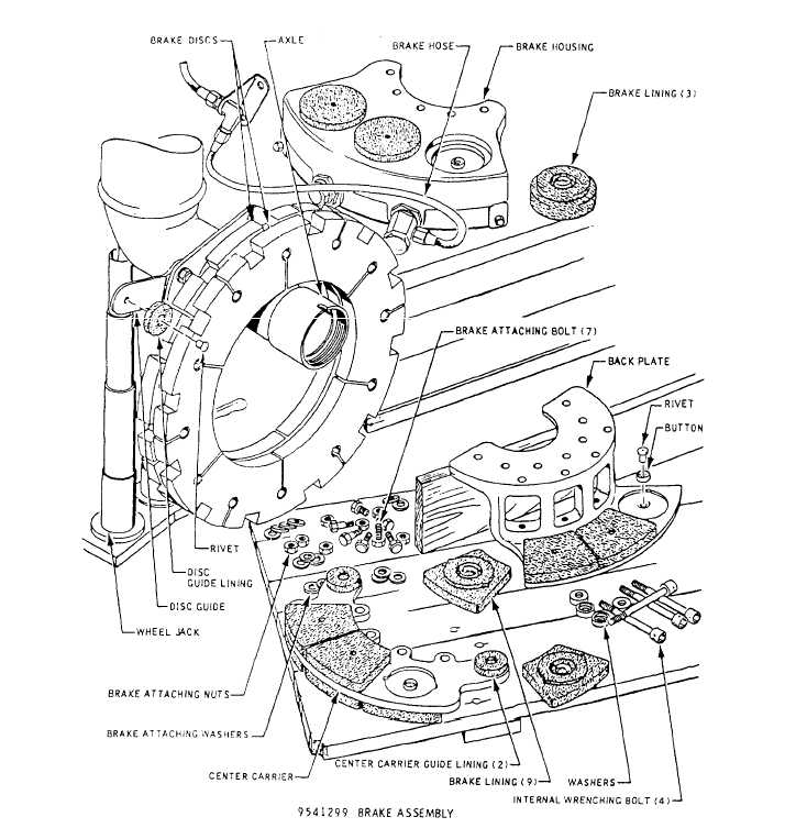
Figure 12-51.-Dual disc brake-repair and parts replacement. |
 
|
|
|