Custom Search
|
|
  |
|
|
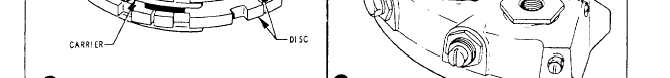
4. Remove the brake linings from the pistons, the brake housing, and the disc guide. 5. Clean the brake assembly components with low-pressure compressed air. Wash all metal parts in P-D-680 cleaning solvent. Dry with compressed air. 6. Check the release units for damage, nicks, and gouges. If damaged, replace the complete release unit. 7. Check the brake housing for cracks and cylinder walls for nicks or other visible damage. Damage will necessitate turning in the complete brake assembly to supply for disposition. 8. Install new linings in the housing cavities and rivet on the disc guide lining. Friction fit will hold the linings in the housing cavities. Do NOT use cement. 9. Install new linings in the piston cavities using brake lining adhesive specified for such use (for example, Pliogrip No. 3). 10. Install the brake disc into the brake housing. 11. Dip brake release unit packings from the cure-date kit into the hydraulic fluid and install on the brake release units. 12. Coat the piston of the release unit with a light coating of hydraulic fluid and install in the housing. Tighten the cylinder heads against the housing as specified in the MIM or the 03 manual. 13. Reinstall the inlet plug, bushing, and bleeder adapter into the housing. Use new packings that have been dipped in hydraulic fluid. 14. Lockwire the cylinder heads, bleed the brake, and test the brake for leakage and proper operation. Test pressure for this brake assembly is 1,100 psi. Hold the pressure for 2 minutes and check the assembly for leaks. Release and reapply the pressure 10 times, and check for proper brake operation and release of the discs. Allow the brake to stand 2 minutes with pressure relieved to check for static fluid leakage. On dual disc brakes, as well as some single disc brakes, the linings may be replaced without disturbing the brake hydraulic system. See figure 12-51. In this example, the shock strut is raised with a wheel jack until the wheel is clear of the ground. The wheel is removed, and the four internal wrenching bolts that attach the brake housing to the backplate are removed. The two setscrews located at each side of the brake housing are unscrewed enough to allow removal of the seven axle flange attaching bolts. Make certain the brake assembly is supported before you remove the bolts, or damage to the brake hose could result. Remove the brake linings from the pistons, center carrier, backplate, and disc guide. Riveted linings must be drilled. Snap-on or friction-fit linings can be easily pried off with a common screwdriver. Remove dirt and other foreign particles from the brake assembly components by the use of low-pressure compressed air. Wear safety eye protection during this operation. Clean the external surfaces of the brake parts with a cloth dampened with P-D-680 cleaning solvent. Replace any brake lining attaching buttons that are damaged. The housing, backplate, center carrier, and all bolts should be inspected for damage, cracks, or leakage, as applicable. lf the brake has hydraulic leakage or if the housing, backplate, or center carrier is damaged or cracked, the complete brake assembly should be replaced and turned in to supply for repair at the next higher level of maintenance. Inspect the disc for minimum thickness, maximum width of the keyways, and warping. Check the disc for warpage by using a straightedge across the face of the disc. Instructions for straightening a warped disc can be found in the applicable 03 manual. Replace a brake disc that is worn excessively. When a brake disc keyway is worn excessively or elongated, inspect the brake disc drive keys within the wheel assembly for damage and security. Replace the drive keys or the wheel if the damage exceeds the limitations specified in the applicable MIM. The new linings are installed in the brake pistons, the center carrier, and the backplate. The disc guide lining is riveted to the disc guide. The pistons are pushed back into the piston housing until a maximum of 1/8 inch of lining is protruding beyond the housing. Assemble the brake on the axle flange, and torque all attaching bolts as well as the four internal wrenching bolts to the specifications provided in the MIM. The fore and aft axle attaching nuts on the brake housing must have their flat surface toward the setscrew on the final torque. The setscrews are tightened against the flat surfaces to safety the nuts. Secure the four internal wrenching bolts with lockwire. The wheel is installed and the shock strut lowered. Perform an operational check to verify proper operation. Specified steps throughout the lining and disc replacement procedures and the final security of all attachments require quality assurance verification as indicated in the MIM.
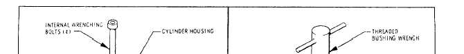
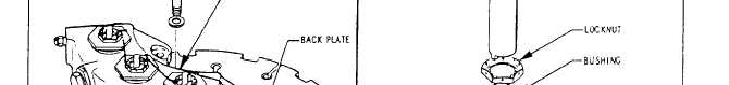
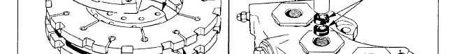
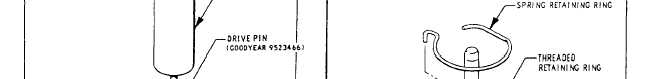
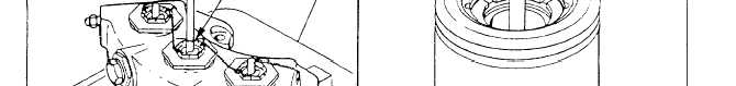
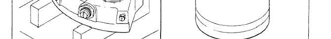
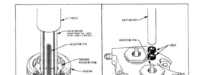
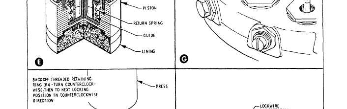
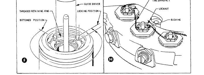
Figure 1252.-Seal replacement and piston return adjustment. Figure 12-52 shows the various steps involved in replacing the piston seals and adjusting the return mechanism. The internal wrenching bolts holding the cylinder housing to the carrier and backplate are removed (view A). The cylinder housing is placed under a press, as illustrated in view B. Use the press and the drive pin to force the adjusting pins through their grips and remove the pistons from the housing. Make sure that the drive pin is centered on the adjusting pinto prevent damaging the adjusting pin packings and grips. Next, cut the lockwire on the locknut. Use the threaded bushing wrench, illustrated in view C, to
Figure 12-52.-Seal replacement and piston return adjustmentContinued. |
 
|
|
|