Custom Search
|
|
  |
|
|
remove the locknuts, bushings, spacers, and grips from the housing. Remove the spring retaining ring from within the piston, as shown in view D. With the linings still attached to the pistons, support the pistons in a press. Use a 3-inch length of 7/8-inch steel tubing to force the guides to the bottom on the adjusting pins, as shown in view E. Hold the guides in the bottomed position and turn the threaded retaining rings clockwise until the rings are snug against the bottom guides. Back off the threaded retaining rings 3/4 of a turn counterclockwise from the bottomed positions and, if necessary, continue turning counterclockwise to
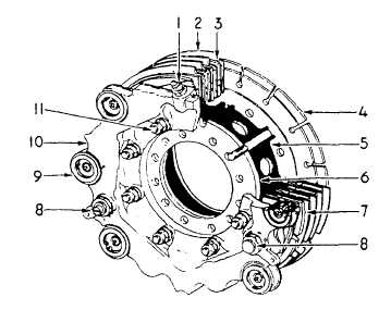
1. Bleeder valve Figure 12-53.-Trimetallic brake assembly. the next locking position, as shown in view F. Secure the threaded retainer with the wire retaining ring. Replace the piston packings with new packings that have been dipped in hydraulic fluid, and ensure that the packings and adjusting pin stems are lubricated with The piston assemblies are then installed in the cylinder housing and forced to the complete brake-off positionsbottomed in the housing cavities. The pistons are supported against their linings to the brake-off position. Use the press and the grip driver, as illustrated in view G, to force the grips, one at a time, over the adjusting pins until they are bottomed. The pistons must remain in the complete brake-off position when the grips are installed. Place the spacers over the adjusting pins and install the bushings fingertight. Hold the bushings in fingertight positions and install and tighten the locknuts. Safety wire the locknuts, as shown in view H.NOTE: On some brake assemblies, the ad-justing pin bushing (adjusting pin nut) is torqued to a specified value.The brake assembly must be tested following reassembly. Connect the brake assembly to a hydraulic supply source. Bleed the brake assembly and apply 600 psi.
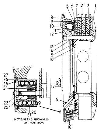
1. Housing backplate 19. Self-adjusting pin 20. Return-spring guide 21. Return spring 22. Self-adjusting pin tube 23. Self-locking nut 24. Split collar grips 25. Retalning ring 26. Spring housing 27. Spring housing bushing Figure 12-54.-Trimetallic brake assembly-cross section. CAUTION Before applying pressure, make sure that the brake is assembled properly with all bolts torqued and brake discs in position. Failure to do so could result in injury to personnel.Hold the test pressure for 2 minutes while you are checking the brake assembly for leaks. Release and apply the pressure 10 times to be sure that the brake functions properly. The brake discs should be free when hydraulic pressure is released. Allow the brake to stand for 2 minutes with pressure released and check for static fluid leakage. If the brake assembly is not to be installed immediately, install any attaching hardware that is part of the assembly, fill with preservative hydraulic fluid, and cap or plug all openings to prevent contamination. |
 
|
|
|