Custom Search
|
|
  |
|
|
CLEANING AND INSPECTION.
Dust
and loose grit are removed by using low-pressure air, and then all parts are cleaned in a P-D-680 cleaning solvent
and dried with a clean, lint-free cloth.
All metal parts are visually inspected for cracks, wear, or other damage, as specified in the "Intermediate Repair" section of the MIM. Some parts may require inspection by one of the nondestructive methods. The return spring is inspected for proper resilience. The amount of force required to move the grips on each tube and grip assembly is checked with a special tube and grip tester. The rotating disc is inspected for cracks, distortion, and thickness. The disc must be replaced if it is worn below 0.2-inch thickness, if it is cracked, or if the friction mix is worn unevenly. The friction mix maybe pitted up to 0.5 square inch in any segment. The stationary disc is inspected for cracks and thickness. If the minimum thickness is less than 0.3 inch or the disc is cracked, it should be replaced. The backplate and pressure plate should be replaced if they are cracked. If the wear pads are worn to less than 0.088-inch tltickness, they should be replaced. WEAR PAD REPLACEMENT. Wear pad re-placement on the pressure plate and the backing plate is authorized. Drill out rivets that hold the worn pads. Discard the worn pads. Check the plates for cracks, deformation, and rivet hole elongation. Use a standard squeeze rivet machine to rivet the replacement wear pads to the plates, using the type of rivet specified in the applicable MIM. The rivet bucktail must be below the surface of the wear pad, Rivets with more than one crack visible in the bucktail or with less than 50 percent of the circumference of the formed head flush with the sides of the countersunk area are not acceptable. The new wear pads must be surface ground to 0. 100-inch thickness, and should be flat within 0.010 inch after grinding. The reworked plates should be vapor degreased to remove all oil and grinding material. The dried plates should be wrapped in clean, heavy paper for protection until they are replaced in the brake assembly. REASSEMBLY. Reassembly of the trimetallic brake is essentially in the reverse order of disassembly. Lubricate the packings, retainers, cylinder walls, and other contacting surfaces within the brake housing with a light coating of MIL-G-8 1322, general-purpose aircraft grease before reassembly. Apply MIL-G-6032B grease to the piston side of the piston insulators. Lubricate the brake housing bolts and the contacting surfaces of the bolt heads with antiseize compound. The coating of these bolts and the contacting surface of the bolt heads, followed by torquing, are referred to in some MIMs as "Lubtork." TESTING. The reassembled trimetallic brake must be tested to ensure the quality of maintenance. Connect the brake assembly to a hydraulic test stand and apply 25 psi to the inlet port. Open the bleeder valve until air-free fluid flows from the valve. Increase the pressure to 1,000 psi for 2 minutes and check for leaks. Relieve and reapply 1,000 psi several times, and then release the pressure slowly to 90 psi. Holding the 90-psi pressure, measure the clearance between the pressure plate and the first rotating disc. Minimum clearance must be 0.065 inch. If used discs were reinstalled, check for proper rotation. Secure the test stand, disconnect the brake, and plug the inlet port to prevent contamination.
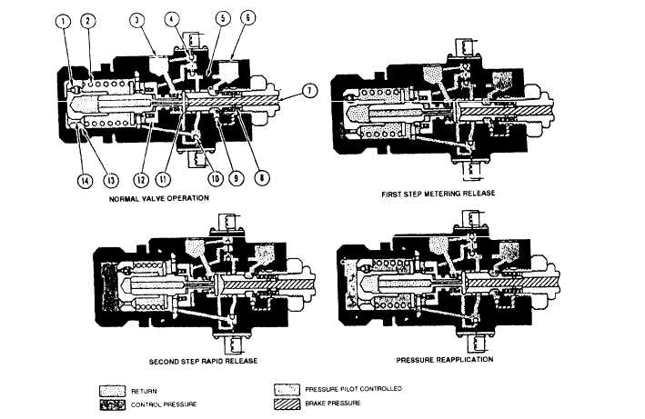
1. Control orifice No. 2 (release) Figure 12-55.-Antiskid control valve schematic. SKID CONTROL SYSTEM MAINTENANCE Learning Objective: Recognize the organizational- and intermediate-level maintenance requirements for the proper operation of the skid control system.An antiskid test set is available for personnel in the AE rating to use on the antiskid system. The operational test normally requires a joint effort on the part of both AM and AE personnel. Organizational maintenance on the antiskid control valve, shown in figure 12-55, is limited to removal and replacement. Intermediate level repair of the valve consists of cure-date seal and parts replacement in accordance with the procedures provided in the "Intermediate Maintenance" section of the MIM. Following repair, the valve must be tested to verify proper operation both hydraulically and electrically. Trouble analysis/troubleshooting of the antiskid system is generally accomplished by personnel of the AE rating. The steps provided for using the antiskid test set will pinpoint the causes for most malfunctions. Those steps that do not meet the specified results are investigated, parts are replaced as necessary, and the complete operational check is repeated to verify that the malfunction has been corrected. |
 
|
|
|