Custom Search
|
|
  |
|
|
HYDRAULIC UTILITY SYSTEMS
MAINTENANCE Learning Objective: Recognize the different procedures.These systems may be powered by the aircraft power or aircraft utility hydraulic systems. Some units receive power throughout the flight, while others are isolated from system pressure to prevent unnecessary loss of hydraulic fluid caused by damage or system malfunction. The systems discussed here are representative of those with which you will most likely be working. In parts of the discussion, values such as tolerances, pressures, and temperatures are given to provide detail in the coverage. You should bear in mind that changes in these values are sometimes necessary because of experience and data gathered from fleet use. When actually performing the maintenance procedures discussed, you should consult the current applicable technical publications for the latest information and exact values to be used. ARRESTING GEAR SYSTEM The arresting gear system controls operation of the arresting hook and the supplementary equipment required to lower and raise the hook for carrier operation. At organizational maintenance levels, maintenance of the arresting gear system consists of servicing the snubber-actuator and bumper assemblies, operational checks, troubleshooting, rigging and adjusting the system, and removal and installation of components within the system. WARNING Before operating the arresting gear, make sure all personnel and equipment are clear of the area through which the gear moves. When checking arresting gear operation, always provide suitable protection for the arresting hook point. Place a sandbag or padding on the deck. Failure to observe proper maintenance procedures could result in damage to aircraft and injury to personnel.Arresting Hook Assembly Inspection The periodic maintenance information cards for each aircraft and MIM provide detailed information on the inspection, replacement, and disposition of arresting hook assemblies. This information is based on a specified number of arrested landings. The inspection and replacement interval is dependent on the type of hook. There are currently three types of arresting hooks. Type I integral type arresting hook is highly heat-treated with an uncoated hook point. Type II integral type has a Metco-coated hook point. Type III detachable hook point is heat-treated, stainless steel or alloy, and coated with Colmony or Metco. As an example, the conditional maintenance requirements cards for a representative aircraft with a type II hook assembly requires inspection of the arresting hook stinger and centering block after 10 recorded arrestments. The inspection consists of the following: 1. Checking the hook shank, centering block and truss members for cracks, misalignment, and obvious damage 2. Checking the stinger (I-beam and hook point) for transverse cracks in the Metco coating, extending to the base metal 3. Chipping or gouging in the cable contact groove 4. Cracks or defective bonding of the Metco coating Any of these conditions are cause for rejection and replacement of the assembly. Following inspection or installation of a new arresting gear assembly, apply grease conforming to that recommended by the applicable MRC and/or the MIM to the cable groove area. Whenever the arresting hook experiences a double wire engagement, strikes the ramp or a deck protrusion, or approaches but does not exceed 100 arrestments, replace designated parts of the complete arresting gear mechanism. The removed parts are forwarded to the designated depot-level maintenance activity for test and overhaul. Include the total number of arrestments on the screening and ready-for-issue tags. This number is necessary so that an accurate account of the total number of arrestments of each assembly can be maintained. Detachable hook points that are removed for inspection after 10 arrestments are reinstalled or replaced with new attaching hardware (nut, bolt, washer, etc.). Install the bolt with the head down and the nut on top. In all cases, periodic maintenance of the arresting hook assemblies should be in accordance with the applicable MIM and/or maintenance requirements cards.
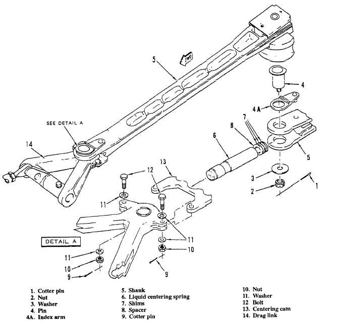
Figure 12-56.Arresting gear mechanism. |
 
|
|
|