Custom Search
|
|
  |
|
|
SHEET METAL FABRICATION Learning Objective: Recognize the terms and procedures for the fabrication of sheet metal parts. To effectively construct and repair parts of an airframe, you must be able to lay out, cut, and form metal. The layout of bend lines must include the allowance for the amount of material used to make the bend in the proper location. The proper fit of the finished part can be ensured if the layout, cuts, and bends are carefully considered before the actual fabrication is started. The procedures and equipment discussed in this chapter are designed to provide accurate and dependable results. The development of a layout on sheet metal is basically the same as the development of blueprints and drawings. For a better understanding of these procedures, you should refer to and Sketching, NAVEDTRA 1OO77-F1.
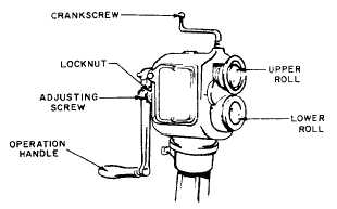
Figure 13-28.-Rotary machine. When you are laying out metal, there are certain precautions that should be observed. In the following paragraphs, some of the more important precautions are discussed. For information on the use of layout tools, you should refer to and Measuring Tools, NAVEDTRA 12085.You should take every precaution to avoid marring aluminum-alloy and steel sheets. To protect the under surface of the material from any possible damage, you should place apiece of heavy paper, felt, or plywood between the material and the working surface. When you are working with a large sheet of material, it is important to avoid bending it. It is a good idea to have someone help you place it on the work surface.A layout fluid should be applied to the surface of the metal so that the pattern will stand out clearly. Any one of several approved fluids may be used. Bluing fluid, a blue dye dissolved in alcohol, is the most commonly used layout fluid. Since it does not protect metal against corrosion or serve as a paint binder, bluing fluid should be removed after use. Either ordinary paint thinner or alcohol may be used to remove it.To begin the layout, you should ensure that one edge of the metal is straight. All measurements can then be based on the straight edge of the sheet. Lines at a known angle or parallel to the straightedge can be made by marking points from a combination square held firmly against the straight edge.
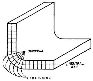
Figure 13-29.-Neutral axis. If it is impossible to obtain a straight edge on a sheet to start a layout or if the distance from the edge is too great, a reference line may be used. The reference line may be made by connecting any two points with a straight line. Perpendiculars may be erected to the reference line by using a compass or dividers. Once the perpendicular is accurately established, it may be used as a basis for almost any layout.A scriber must never be used for drawing lines on aluminum or magnesium except to indicate where the metal is to be cut or drilled. All other lines should be drawn with a soft-lead pencil. The pencil mark should be removed from aluminum and magnesium to prevent an electrolytic action that will eventually cause corrosion. It can be removed with isopropyl alcohol or MEK. If you fold a piece of metal along a sharp line made with a scriber, the scribed line will weaken the metal and possibly cause it to crack along the bend. If it does not crack at the time of bending, it is very susceptible to cracking at a later time when failure of the part could be dangerous. |
|
|
|