Custom Search
|
|
  |
|
|
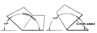
BEND ALLOWANCE When you are bending metal to exact dimensions, the amount of material needed to form the bend must be known. The term for the amount of material that is actually used in making the bend is bend. Approximately halfway between these two extremes lies a space that neither shrinks nor stretches. This space is known as the neutral line or neutral axis. Figure 13-29 shows the neutral axis of a bend. It is along this neutral axis that bend allowance is computed. BEND ALLOWANCE TERMS You should be familiar with the following terms related to a bending job. Figure 13-30 shows the meaning of some of these terms. Bend allowance. The amount of material consumed in making a bend. Closed angle. An angle that is less than 90 degrees when measured between legs. When the closed angle is 45 degrees, the amount of bend is 180 minus 45 or 135 degrees. See figure 13-31.
Figure 13-30.-Bend allowance terms. Open angle. An angle that is more than 90 degrees when measured between legs or less than 90 degrees when the amount of bend is measured. Flange. The shorter part of a formed anglethe opposite of leg. If each side of the angle is the same length, then each is known as a leg. Flat. The flat portion, or flat, of a part is that portion not included in the bend. It is equal to the base measurement minus the setback. K number. A K number is one of 179 numbers on the K chart that corresponds to one of the angles between 0 and 180 degrees to which metal can be bent. When metal is to be bent to any angle other than 90 degrees (K number of 1.0), the corresponding K number is selected from the chart and multiplied by the sum of the radius and the thickness of the metal. The product is the amount of setback for the bend. Leg. The longer part of a formed angle. Bend line. The bend line (also called the brake or sight line) is the layout line on the metal being formed that is set even with the nose of the brake, and it serves as a guide in bending the work. Before forming a bend, the metalsmith must decide which
Figure 13-31.-Open and closed angles. end of the material can be most conveniently inserted in the brake. The bend line is then measured and marked with a soft-lead pencil from the bend tangent line closest to the end that is to be placed under the brake. This measurement should be equal to the radius of the bend. The metal is then inserted in the brake so that the nose of the brake will fall directly over the bend line. See figure 13-32. Bend tangent line. The line at which the metal starts to bend and the line at which the metal stops curving. All the space between the bend tangent lines is the bend allowance. Mold line. The line formed by extending the outside surfaces of the leg and the flange. (An imaginary point from which real base measurements are provided on drawings.) Base measurement. The base measurement is the outside dimension of a formed part. Base measurement will be given on the drawing or blueprint, or it may be obtained from the original part.
Figure 13-32.-Locating bend lines in a brake. Radius. The radius (R) of the bend is always to the inside of the metal being formed unless otherwise stated. The minimum allowable radius for bending a given type and thickness of material should always be determined before you proceed with any bend allowance calculations. Setback The setback (SB) is the distance from the bend tangent line to the mold point. In a 90-degree bend, SB = R + T (radius of the bend plus thickness of the metal). The setback dimension must be determined prior to making the bend because setback is used in determining the location of the beginning bend tangent line. |
 
|
|
|
|
|
Integrated Publishing, Inc. - A (SDVOSB) Service Disabled Veteran Owned Small Business
|