Custom Search
|
|
  |
|
|
Layout for Repair Information needed to fabricate replacement parts is usually found on blueprints, while information concerning repairs may be found in the aircraft structural repair manual. The manual contains information on extrusions and the necessary data for the fabrication of various sheet metal equivalents. The aircraft structural repair manual will indicate the type of material to be used in each repair. If the correct material is not available, the for Structural Repair acceptable substitute. The fabrication of sheet metal parts for internal structural repair requires careful adherence to the accepted standards of aircraft sheet metal work. This includes accurate calculation of bend allowance and careful layout of all dimensions. Layout is the interpreting and transcribing of information from blueprints, drawings, or written instructions to the metal that will be made into a part for an aircraft. If several parts are to be fabricated, the dimensions may be transferred to a template. Working from a template ensures a higher degree of uniformity and speeds production. The procedure for making a layout either for a template or for the actual part is essentially the same. Layout of a part or a template consists principally of marking the flat sheet so that all drilling, cutting, bending, and forming operations are indicated on the sheet. It is a comparable level 3 drawing that has been marked up in sufficient detail to clearly indicate the fabrication requirements for each piece/part. The sheet metal layout may be made from printed instructions, but it is more often made directly from the blueprint. Accuracy in all details is essential. You should not transfer dimensions directly from the blueprint to the layout because the print material may have stretched or shrunk, which causes minor distor-tion of the dimensions. Measurements indicated on the blueprint are made on the layout. Details are often left out and must be developed in the shop. You may, for example, find that you must add several dimensions, and then figure the bend allowance for the material consumed in each bend before you are able to lay out the overall length or width of a part. On very accurate layouts, a magnifying glass is frequently used as an aid to precision work. A magnifying glass enlarges the graduations on a scale and makes them easier to read. It helps locate center punch marks, and it allows a close inspection of the accuracy of the completed layout. Earlier in this chapter, we discussed the layout procedures for sheet metal fabrication. These same procedures are used to lay out the material that is going to be used to make the repair.
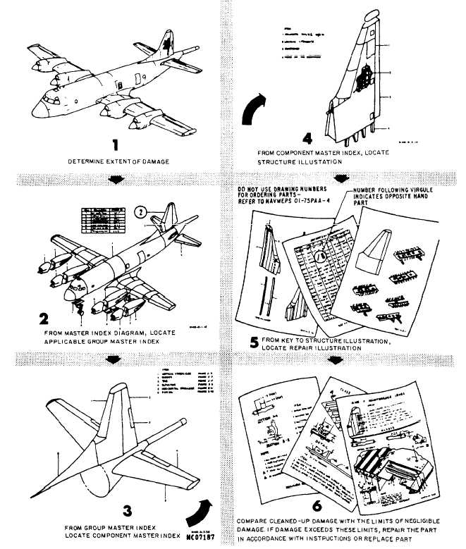
Figure 13-57.How to use a structural repair manual. In the layout of a part, you should plan the bending and forming operations so that each step is made in the proper sequence. If the steps are not made in the proper sequence, the part may become so bulky that it will be impossible to insert in the brake to make the final bend. Since layout of replacement parts involves the interpretation of blueprints, you should review Blueprint Reading and Sketching, NAVEDTRA 10077-F1. |
 
|
|
|
|
|
Integrated Publishing, Inc. - A (SDVOSB) Service Disabled Veteran Owned Small Business
|