Custom Search
|
|
  |
|
|
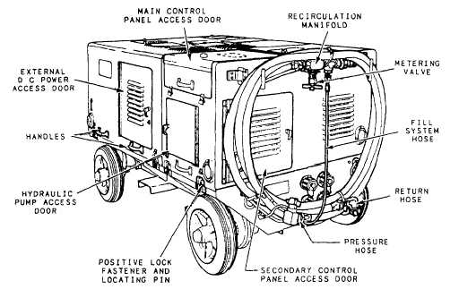
PORTABLE HYDRAULIC TEST STANDS Several different models of portable hydraulic test stands are currently used in the fleet. The primary function of these stands is to provide external ground power to aircraft hydraulic systems. The stands vary as to fluid-flow capabilities, source of prime power, and manufacturer. A complete description of specific operating instructions for portable hydraulic test stands is not contained in this section. However, some of the common test stands are discussed, so you will have some knowledge of portable hydraulic test stands. NOTE: The AHT-64 test stand is being replaced by the A/M27T-5 test stand; therefore, it is not covered in this chapter. A/M27T-3 Portable Hydraulic Power Unit The A/M27T-3 power unit is designed to be
directly connected into the aircraft hydraulic system,
and it provides the means to accurately check out the operating characteristics of the hydraulic system and components at pressures up to 4,500 psi. This can be accomplished without running the aircraft engine. The power unit is used at the organizational level for all aircraft where requirements for hydraulic fluid flow are not significant. The power unit consists of an electrically powered, pump impelled, hydraulic system housed in an aluminum frame structure and mounted on casters. The structure is mounted on two swivels and two fixed casters, and is equipped with a manual tow bar for ease of mobility. It also has a hand-operated brake to prevent unintended movement of the power supply. The control panel is mounted on one end of the power unit. Other controls and components are accessible through removable side panels. The power unit is equipped with an electrical cable and hydraulic hoses that are stored on a rack attached to one end of the unit when they are not in use. The power unit consists of two basic systems: a hydraulic system and an electrical system. Hydraulic and electrical schematics are provided on etched plates permanently attached to the unit. For a more detailed description of this power unit and its operating procedures, refer to the NAVAIR 17-15BF-76. |
 
|
|
|
|
|
Integrated Publishing, Inc. - A (SDVOSB) Service Disabled Veteran Owned Small Business
|