Custom Search
|
|
  |
|
|
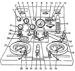
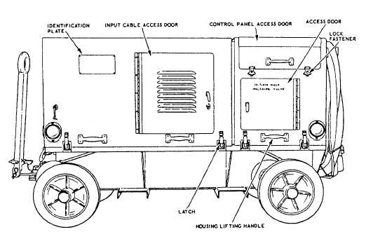
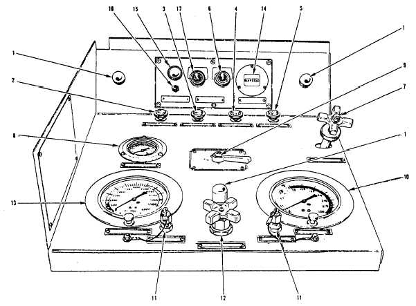
A/M27T-5 Portable Hydraulic Power Supply The A/M27T-5 portable hydraulic power supply (fig. 4-11), made by Janke and Company, Inc., is replacing the AHT-64 hydraulic test stand made by Teledyne Sprague Engineering. The A/M27T-5 is a modified AHT-64 portable, table hydraulic power supply unit. It is a self-contained, diesel powered, trailer-mounted unit capable of providing a source of hydraulic fluid at controlled pressures and flow rates from 0 gpm at 0 psi to 24 gpm at 3,000 psi, or 13 gpm at 5,000 psi under ambient temperatures of 25F to +115F and relative humidity of 95 percent. The Model 3-53 Detroit diesel engine is used in the A/M27T-5. Minor changes were made to the physical location of system components to make maintenance easier. See figure 4-12 for a view of the A/M27T-5 central panel. Table 4-5 explains the functions of each control and indicator on the panel. AHT-63 Portable Hydraulic Test Stand The Portable Hydraulic Test Stand AHT-63 (fig. 4-13) is powered by an electric motor. The motor operates at 50 hp, 3,520 rpm, and is dripproof: it is capable of operating on 220/440-volt, three-phase, 60-Hz (cycle) current. The motor is a double-end shaft type. One end drives the high-pressure pump, and the other end drives the oil cooler fan. The motor is equipped with a magnetic starter, a thermal overload relay for protection, a reverse phase relay to protect the pump unit from reverse rotation caused by incorrect electrical power phasing, and a low-pressure switch to stop the motor when boost pressure is too low at the high-pressure pump inlet. It has 50 feet of neoprene-covered, three-phase electric cable with ground wire, which operates at either 220 or 440 volts. The control circuit is further protected by a circuit breaker and fuses. PRINCIPLES OF OPERATION. The AHT-63 and A/M27T-5 operate in basically the same manner. They differ in their starting and stopping procedures and the electrical outlet used to furnish power to the electric motor. Before you use the AHT-63 test stand, you need to know how it works and the location and function of all switches, controls, and instruments. See figure 4-14 and table 4-6. For specific instructions on its use, refer to the Handbook of Operation, Service, and Overhaul Instruction, NA 17-15BF-65, and the applicable MIM.MINIMUM REQUIREMENTS. Before you operate the portable hydraulic test stand, follow the specific instructions for its inspection, turnup, aircraft
Figure 4-12.A/M27T-5 main control panel controls and indicators.Table 4-5.A/M27T-5 Main
Control Panel Controls and Indicators
Table 4-6.AHT-63 Control Panel Controls and InstrumentsContinued
connection, and operation from the applicable maintenance manuals. You should know some of the minimum general requirements about the use of all portable test stands. Locate the test stand so there is adequate room and ventilation, and where engine heat can be dissipated. Set parking brakes securely and open all necessary access doors. Check the hydraulic fluid level of the test stand reservoir. It should be three-fourths full, as indicated on the gauge. Add fluid if required. Check fuel gauge, radiator level, and engine oil level in engine-driven stands. Make sure that they are adequate for the anticipated operating period. Check the power connections in electric-powered stands for correct phasing and frequency. Check the pointers of all other gauges; they should beat or near zero. Clean and connect the service ends of the external pressure and return line hoses to the hose storage (recirculation) manifold on the equipment. If the manifold is equipped with a shutoff valve, place the valve in open position. Start test stand engine (or motor) according to the applicable operating instructions. Allow the engine to warm up to its normal operating temperature. Recirculation clean and deaerate the hydraulic fluid in the test stand. Perform both operations at the same time. NOTE: When actually cleaning and deaerating the test stand, you should follow the procedures contained in the applicable manuals.Set up the test stand to provide fluid flow from the internal reservoir through the external service hoses and interconnecting manifold. Place the pump pressure compensator at its lowest setting, and make sure that the manifold and service outlet valves (if present) are in the open position. The high-pressure gauge should indicate a value less than 600 psi. Allow the test stand to recirculation clean for 3 to 5 minutes. Monitor the fluid temperature throughout the cleaning cycle. Make sure that maximum operating limits are not exceeded. Monitor all filter differential pressure indicators, particularly those associated with the 3-micron filter assemblies. If you see an indication of a loaded filter after the fluid reaches normal operating temperature (85F minimum), shut down the test stand and have replacement filter elements installed. On test stands that have a fluid sight glass and manual air bleed valve, periodically operate the valve and monitor the sight glass throughout the cleaning cycle to eliminate visible indications of entrapped air. When recirculation cleaning and deaeration are complete, analyze the hydraulic fluid for contamin-nation Terminate the fluid flow to the external service hoses in preparation for connecting them to the aircraft. Disconnect the service hoses from manifold assembly and reinstall the manifold dust covers. |
 
|
|
|