Custom Search
|
|
  |
|
|
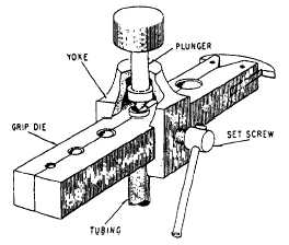
Flared Fitting There are two types of flared tubing jointsthe single-flared joint and the double-flared joint. The single-flared tube joint is used on all sizes of steel tubing and 5052 aluminum alloy tubing that conforms to Federal Specification WW-T-700/6 with 1/2 inch or larger outside diameter, Use the tube flaring tool (fig. 6-12) to prepare tube ends for flaring. Check tube ends for roundness, square cut, cleanliness, and no draw marks or scratches. Draw marks can spread and split the tube when it is flared. Use a deburring tool to remove burrs from the inside and outside of the tubing. Remove filings, chips, and grit from inside the tube. Clean the tube. Slip the fitting nut and sleeve onto the tube. Place the tube into the proper size hole in the grip die. Make sure the end of the tube extends 1/64 inch above the surface of the grip die. Center the plunger over the end of the tube and
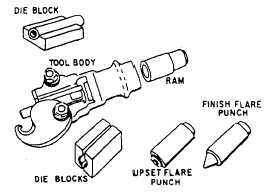
Figure 6-12.Tube flaring toot (single-flare). tighten the yoke setscrew to secure the tube in the grip die and hold the yoke in place. Strike the top of the plunger several light blows with a hammer or mallet, turning the plunger a half turn after each blow. Loosen the setscrew and remove the tube from the grip die. Check to make sure that no cracks are evident and that the flared end of the tube is no larger than the largest diameter of the sleeve being used. The double-flare tube joint is used on all 5052 aluminum alloy tubes with less than 1/2-inch outside diameter, except when used with NAS 590 series tube fittings and NAS 591 connectors or NAS 593 con-nectors. Aluminum alloy tubing used in low-pressure oxygen systems or corrosion-resistant steel used in brake systems must be double flared. Double flare reduces the chance of cutting the flare by overtightening. When fabricating oxygen lines, make sure that all tube material and tools are kept free of oil and grease. Use the tube flaring tool (fig. 6-13) to prepare tube ends. Check tube end for roundness, square cut, cleanliness, and make sure there are no draw marks or scratches. Draw marks can split the tubing when it is flared.
Use a deburring tool to remove burrs from the inside and outside of tube. Remove filings, chips, and grit from inside the tube. Clean the tube. Select the proper size die blocks, and place one-half of the die block into the flaring tool body with the countersunk end towards the ram guide. Install the nut and sleeve, and lay the tube in the die block with 1/2 inch protruding beyond countersunk end. Place the other half of the die block into the tool body, close latch plate, and tighten the clamp nuts fingertight. Insert the upset flare punch in the tool body with the gauge end toward the die blocks. The upset flare punch has one end counterbored or recessed to gauge the amount of tubing needed to form a double lap flare. Insert the ram and tap lightly with a hammer or mallet until the upset flare punch contacts the die blocks, and the die blocks are set against the stop plate on the bottom. Use a wrench to tighten the latch plate nuts alternately, beginning with the closed side, to prevent distortion of the tool. Reverse the upset flare punch; insert the upset flare punch and ram into the tool body. Tap lightly with a hammer or mallet until the upset flare punch contacts the die blocks. Remove the upset flare punch and ram. Insert the finishing flare punch and ram. Tap the ram lightly until a good seat is formed (fig. 6-14). Check the seat at intervals during the finishing operation to avoid overseating. |
 
|
|
|
|
|
Integrated Publishing, Inc. - A (SDVOSB) Service Disabled Veteran Owned Small Business
|