Custom Search
|
|
  |
|
|
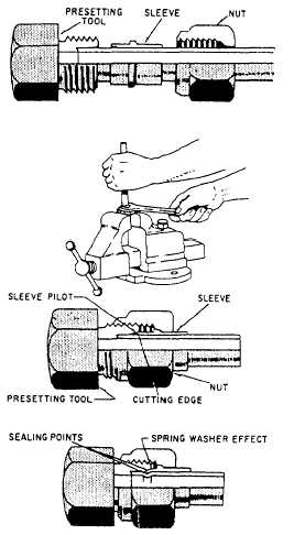
Flareless Fitting Preparing tube ends for flareless fitting requires a presetting operation whereby the sleeve is set onto the tubing. Presetting is necessary to form the seal between the sleeve and the tube without damaging the connector. Presetting should always be accomplished with a presetting tool, such as the one shown in figure 6-15. These tools are machined from tool steel and hardened so that they may be used with a minimum of distortion and wear.
NOTE: A flareless-tube connector may be used as a presetting tool in case of an emergency. However, when connectors are used as presetting tools, aluminum connectors should be used only once, and steel connectors should not be used more than five times.Special procedures are used in the presetting operation. Select the correct size presetting tool or a flareless fitting body. Clamp the presetting tool or flareless fitting body in a vise. Slide a nut and then a sleeve onto the tube, and make sure the pilot and cutting edge of the sleeve points toward the end of tube. Select the lubricant from table 6-4, and lubricate fitting threads, tool seat, and shoulder sleeve. Place the tube end firmly against the bottom of the presetting tool seat, while slowly screwing the nut onto the tool threads with a wrench until the tube
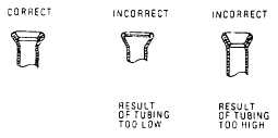
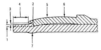
Figure 6-16.Preset sleeve. cannot be rotated with thumb and fingers. At this point the cutting edge of the sleeve is gripping the tube and preventing tube rotation; the fitting is ready for the final tightening force needed to set the sleeve on the tube. Tighten the nut to the number of turns specified in NAVAIR 01-1A-20.After presetting, unscrew the nut from the presetting tool or flareless fitting body; check the sleeve and tube (fig. 6-16). Sleeve cutting lip should be imbedded into the tubes outside diameter between 0.003 inch and 0.008 inch, depending on size and tubing material. A lip of tube material will be raised under the sleeve pilot. The sleeve pilot should contact or be quite close to the outside diameter of tube. The tube projection from the sleeve pilot to the tube end should be as listed in table 6-5. The sleeve should be bowed slightly. The sleeve may rotate on tube and have a maximum lengthwise movement of 1/64 inch. The sealing surface of the sleeve, which contacts theTable 6-5.Tube Projection
From Sleeve Pilot 24-degree angle of fitting body seat, should be smooth, free from scores, and should not show lengthwise or circular cracks. Crazing cracks in finish are not harmful to safety or function of fitting. Minimum internal tube diameter should not be less than values shown in table 6-6.Table 6-7.Alternate Cleaning Solvents for Tubing and Tube Assemblies
|
|
|
|