Custom Search
|
|
  |
|
|
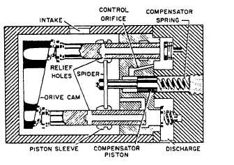
Pressure Control. A
schematic diagram of the pressure
control mechanism is shown in figure 7-19. Pressure
is bled through the control orifice into the
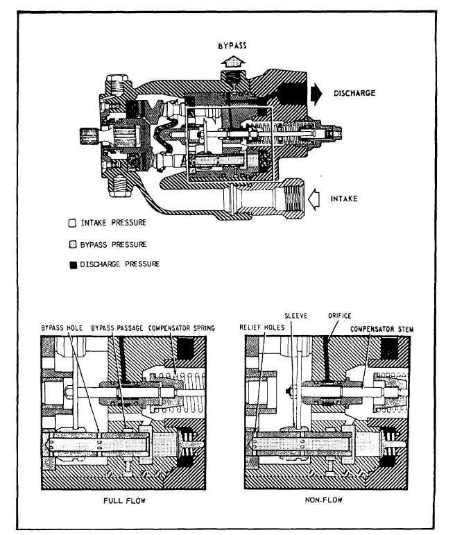
pressure compensator cylinder, where it moves the compensator piston against the force of the calibrated control (compensator) spring. This motion, transmitted by a direct mechanical linkage, moves sleeves axially on the piston, thereby varying the time during which relief holes are covered during each stroke.Fluid flows through the hollow pistons during the forward stroke and escapes out the relief holes until they are covered by the piston sleeves. The effective piston stroke (delivery) is controlled by the piston sleeve position. During nonflow requirements, only enough fluid is pumped to maintain system pressure against leakage.During normal pump operation, three conditions may existfull flow, partial flow, and zero or nonflow. During full flow operation (fig. 7-20), fluid enters the intake port and is discharged to the high-pressure side past the pump checks by the reciprocating action of the pistons. Piston sleeves cover the relief holes for the entire pressure stroke. During partial flow, system pressure is sufficient (as bled through the orifice) to move the compensator stem against the compensator spring force. If system pressure continues to build up, as under nonflow conditions, the stem will be moved further until the relief holes are uncovered for practically the entire piston stroke. Relief holes will be covered only for the stroke necessary to maintain pressure against system leakage and to produce adequate bypass flow. Bypass. The bypass system is provided to supply self-lubrication, particularly when the pump is in nonflow operation. The ring of bypass holes in the pistons are aligned with the bypass passage each time a piston reaches the very end of its forward travel. This pumps a small quantity of fluid out the bypass passage, back to the supply reservoir, and provides a constant changing of the fluid in the pump. The bypass is designed to pump against a considerable back pressure for use with pressurized reservoirs. Maintenance. Line maintenance of the Stratopower pump is limited to operational checks, and checking for leaks and loose fittings. Malfunctioning pumps should be removed and replaced. In removing a pump, always maintain its alignment until the drive shaft is fully withdrawn from the driving element. Never pick up or carry a pump by the drive shaft extension. Before installing a pump, the pump and its attached hose assemblies must be primed (filled with fluid). During installation, the pump must be continuously supported with its shaft parallel to the mounting studs, and the splines must mesh with the driving element.If the pump drive shaft does not engage the driving element, preventing the pump from sliding into place, the drive shaft should be manually rotated until the two splined drive shafts mate. |
|
|
|