Custom Search
|
|
  |
|
|
PISTON-TYPE PUMP (VICKERS ELEC-TRIC MOTOR-DRIVEN
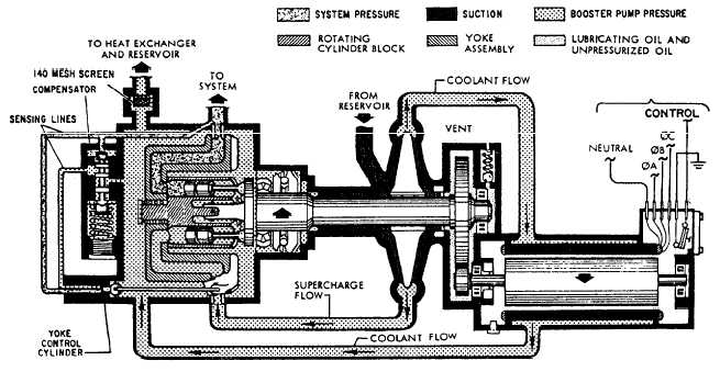
VARIABLE DIS-PLACEMENT). This type of pump is used in some of the Navys most modern aircraft. Motor-driven variable displacement pumps have several advantages over the engine-driven models. Some of these advantages are as follows: 1. Ease of installation and removal due to the accessibility of the component. 2. Constant speed of the drive shaft. 3. Eliminates the need of using a test stand to drop check the landing gear and perform operational checks of other actuating systems. NOTE: Hydraulic test stands are seldom used on aircraft that incorporate this type of pump because foreign particles could be transferred from the test stand to the aircraft, thus contaminating the hydraulic system. 4. The pump assembly contains an internal centrifugal boost pump, which provides a positive fluid pressure at the suction port of the variable displacement pump. The only disadvantages of the pump are the size of the complete assembly and its weight. For this reason, this type of pump is used in patrol and transport aircraft. There are other features incorporated in the motor-driven variable displacement pump that you should know about. A thermal protector manual reset button is installed on the end of the motor, which is concealed by a cover plate. See figure 7-21. This thermal protector is a safety device that protects the motor from overheating. The reset button will open and stop the motor when the temperature exceeds 380 10F. If the motor does not restart after cooling, the cover plate over the reset button should be removed and the reset button reset manually. If the motor still fails to start, the motor pump assembly should be replaced. The motor-driven variable displacement pump suction line is connected from the reservoir to the suction port of the pump assembly, where fluid is ported into the center of a centrifugal pump scroll. The scroll is located between the main pump case and the motor reduction gearbox of the pump assembly. See figure 7-21. The scroll houses a centrifugal booster pump, which is mounted directly on the main pump shaft. The constant-speed motor turns the pump shaft through reduction gears at 3,200 rpm, which is sufficient to boost the fluid pressure about 15 to 20 psi above the existing reservoir pressure. The output of this integral pump is directed to two points on opposite sides of the scroll housing. See figure 7-22. One delivery point provides a constant flow of hydraulic fluid for motor cooling through an internal
passage. Finned baffle-like passages direct this flow around the motor through the hollow-walled motor case, after which it is directed by an external line into the case of the piston pump. This constant flow through the low-pressure chamber of the main pump cools and lubricates all of its moving parts. It also picks up "blow-by" oil that escapes past the high-pressure pump pistons, and is discharged through a coarse-screen filter cartridge installed in the case drain port. The pumps coolant flow is routed through the aircrafts heat exchanger and back to the reservoir. The second delivery point from the integral centrifugal pump is directed from the centrifugal pump scroll at positive pressure to the intake port of the high-pressure pump. As you can see in figure 7-22, the Vickers motor-driven variable displacement design is similar to other engine-driven designs. The rotating assembly consists of a baseplate, to which nine piston rods are joined. The assembly turns in a fixed plane. Also turning with it is a cylindrical nine-piston block fitted inside a nonrotating yoke. The yoke is pivot-mounted to the pump case, and has an offset attachment for a compensator piston rod that controls the yokes attitude. If the yoke is not deflected, the cylinder block containing the pistons will rotate in a plane parallel to the baseplate, thus producing no stroke. The yoke can be tilted to displace the pistons, reaching maximum stroke when the yoke is tilted 30 degrees from the plane of rotation of the baseplate. The pump compensating mechanism receives a feedback signal of system pressure, and adjusts the pump output by tilting the yoke a prescribed amount to provide more or less flow. Whereas engine-driven pumps are generally rated to produce a given pressure and flow at a nominal drive speed, the electric motor-driven pump has a fixed rotational speed and a special compensating mechanism that enables the pump to provide 6 gpm (gallons per minute) at 2,950 to 3,000 psi. It will provide more flow as system pressure drops, reaching a maximum flow of 8 gpm at 2,200 psi. The accelerated flow enables the system to maintain normal speed of many actuators in use simultaneously.
Figure 7-23 shows the three phases of pump compensation in a pressure buildup order, starting at low pressure and increasing to full system pressure. As shown in view (A), the yoke control piston is spring loaded to hold the displacement yoke at its maximum displacement angle of 30 degrees. This spring is opposed by the existing system pressure, which acts at all times on the "constant horsepower" piston area; however, the hydraulic force will not be sufficient to move the yoke control piston until the actuating pressure (system pressure) builds up to 2,200 psi. Thus, the cylinder block will be canted to its maximum angle, and the pump will deliver its maximum flow, 8 gpm, when system pressure is less than 2,200 psi. View (B) of figure 7-23 shows how the yoke con-trol piston responds to system pressure fluctuations in the 2,200 to 2,950 psi range. Assuming that system pressure is steadily increasing, the displacement yoke angle will decrease from the 30-degree full displacement angle to approximately 22 degrees, which will produce 6 gp at 2,950 psi. View (C) of figure 7-23 shows how the spring load on the compensator spool is overcome by system pressure in excess of 2,950 psi, and the displaced spool meters pressure to the "cutoff" area of the yoke control piston. This pressure will act with the "constant hp" force on the piston, and with increasing pressure, the piston will move rapidly from the 22-degree displacement angle at 2,950 psi to approximatey 0 degrees at 3,000 (plus 150, minus 0) psi. When full pressure exists, the hydraulic power output will be the minimum required to replace fluid that leaks internally. The gearbox installed between the motor and pump contains lubricating fluid for internal lubrication, a dipstick for checking its fluid level, fill port to replace fluid, drain port to drain fluid during maintenance, and a relief valve to allow excess fluid to be relieved overboard. The pump gearbox is drained and reserviced with clean hydraulic fluid as follows: 1. Remove the magnetic drain plug and catch the fluid in a suitable container. 2. Inspect the magnetic plug for foreign particles that may have accumulated during periods of operation. Particles that look and feel like "fuzz" are considered acceptable; however, particles containing metal "slivers" require pump overhaul. 3. Remove the filler plug, and flush the gearbox with hydraulic fluid. 4. Clean the magnetic plug, install with a new gasket, and lockwire after replacing. 5. Refill gearbox with hydraulic fluid. 6. Install filler plug and dipstick, using new gaskets. Also, the pump pressure line, fitting, and filter screen are removed. The filter screen is cleaned, using Dry-Cleaning Solvent P-D-680, and reinstalled using a new gasket. The pump pressure line is reinstalled and an operational check performed. NOTE: Hydraulic pumps that are not functioning properly can represent a serious source of contamination in an operating hydraulic system. Hydraulic contamination is discussed in chapter 4 of this TRAMAN. |
 
|
|
|
|
|
Integrated Publishing, Inc. - A (SDVOSB) Service Disabled Veteran Owned Small Business
|