Custom Search
|
|
  |
|
|
CHEMICAL AIR DRIER. Chemical
air driers are installed in air
systems to absorb moisture that may
collect from air entering the system. The main parts
of the air drier, shown in figure 7-8, are the housing,
desiccant cartridge, filter (porous bronze), and
the spring. To ensure proper filtering, the air must
pass through the air drier in the proper direction. The
correct direction of flow is indicated by an arrow and
the wordflow printed on the side of the cartridge. Preventive
maintenance of this component consists
of replacing the cartridge when it becomes saturated.
Maintenance should be accomplished in accordance
with instructions provided in the applicable
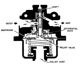
maintenance instruction manual (MIM). AIR PRESSURE REGULATORS. Air pressure used in pressurizing hydraulic reservoirs must be controlled within safe limits. Specific pressure requirements vary between aircraft. In some aircraft, the air pressure is controlled by an air pressure regulator (fig. 7-9). This regulator normally maintains 40 psi pressure in the reservoir. It also incorporates a relief valve to relieve excessive pressure and a differential valve to allow equalization
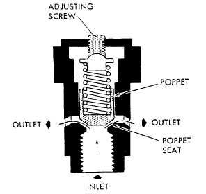
AIR RELIEF VALVE. An air relief valve is normally incorporated in the air portion of the hydraulic power system to relieve excessive air pressure entering the reservoir due to a mal-functioning air pressure regulator. The relief valve shown in figure 7-10 is cylindrical in shape and consists of a housing, poppet, spring, and adjusting screw. This valve may be mounted directly to the reservoir or in a line leading from the reservoir, depending on the aircraft system design. During operation, air pressure enters the inlet port and contacts the poppet surface. When system air pressure increases to 50 psi, the poppet is forced off its seat, which allows excessive air pressure to be exhausted to the atmosphere. When system pressure is lowered to 49 psi, the poppet spring tension overcomes system pressure and reseats the poppet, thus closing the valve. Maintenance of the valve usually includes the replacement of all seals and the adjustment of its controlling pressures. This valve is designed to relieve at a cracking (just open) pressure of 50 psi; the reseating pressure is 49 psi. The valve will operate at full flow when the pressure reaches 60 psi. All pressure adjustments of relief valves must be performed on a test bench. You can control valve pressures by adjusting the adjusting screw on the valve until the proper settings are obtained.
AIR BLEEDER VALVE. During hydraulic system maintenance, it is necessary to relieve reservoir air pressure to assist in the installation and removal of components, lines, etc. An air bleeder valve is incorporated within the reservoir air system to avoid disassembly of lines or units. A similar valve may be incorporated in reservoir return lines to provide a means for bleeding air from returning fluid. This type of valve is small in size and has a push button installed in the outer case. Figure 7-11 shows a full view schematic drawing of a bleeder valve. The valve is made up of a body, spring, poppet, and push button. When the bleeder valve push button is depressed, pressurized air from the reservoir flows through the valve to an overboard vent, until the air pressure is depleted or the button is released. When the button is released, the internal spring causes the poppet to return to its seat. In case of malfunction, this type of valve is replaced with a new valve. SYSTEM OPERATION. During normal operation, the pressurizing air source comes from engine bleed air. See figure 7-7. This bleed air is routed through a poppet-type, one-way check valve to the chemical drier. The chemical drier conditions the air by absorbing its moisture. Conditioned air is then routed through a poppet check valve to the system air pressure regulator. The regulator decreases engine bleed air pressure to a desired working pressure. As air pressure leaves the regulator, it enters the reservoir and acts on its piston, which, in turn, transmits force to the fluid. If malfunction of the regulator causes excessive reservoir air pressure, an air relief valve will open at a preset pressure and exhaust excessive air overboard. Fluid under pressure in the reservoir provides a positive flow of fluid through a one-way check valve to the suction port of the hydraulic pump, thus preventing pump cavitation or starvation.
|
 
|
|
|
|
|
Integrated Publishing, Inc. - A (SDVOSB) Service Disabled Veteran Owned Small Business
|