Custom Search
|
|
  |
|
|
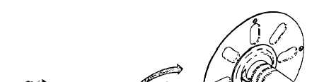
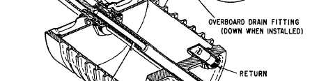
Fluid-Pressurized Reservoirs Some aircraft hydraulic systems use fluid pressure for pressurizing the reservoir. The reservoir shown in figure 7-12 is a fluid-pressurized reservoir. This reservoir is divided into two chambers by a floating piston. The floating piston is forced down-ward in the reservoir by a compression spring within the pressurizing cylinder and by system pressure entering the pressurizing port of the cylinder. The pressurizing port is connected directly to the pressure line. When the system is pressurized, pressure enters the pressure port, thus pressurizing the reservoir. This pressurizes the pump suction line and the reservoir return line to the same pressure. Positive pressure prevents pump starvation. The reservoir shown in figure 7-12 has five ports-pump suction, return, pressurizing, overboard drain, and bleed port. Fluid is supplied to the pump through the pump suction port. Fluid returns to the reservoir from the system through the return port. Pressure from the pump enters the pressurizing cylinder in the top of the reservoir through the pressurizing port. The overboard drain port is for the purpose of draining the reservoir, when necessary, while performing maintenance. The bleed port is used as an aid in servicing the reservoir. When you service a system equipped with this type of reservoir, place a container under the bleed drain port. The fluid should then be pumped into the reservoir until air-free fluid flows through the bleed drain port. The reservoir fluid level is indicated by the markings on the part of the pressurizing cylinder that moves through the reservoir dust cover assembly. See figure 7-12. There are three fluid level markings indicated on the cover: full at zero system pressure (FULL ZERO PRESS), full when system is pressurized (FULL SYS PRESS), and REFILL. When the system is unpressurized and the pointer on the reservoir lies between the two FULL marks, a marginal reservoir fluid level is indicated. When the system is pressurized and the pointer lies between REFILL and FULL SYS PRESS, a marginal reservoir fluid level is also indicated.
PUMPS All aircraft hydraulic systems have one or more power-driven pumps and may have a hand pump as an additional source of power. Power-driven pumps are the primary source of energy, and may be either engine-driven or electric-motor driven. As a general rule, motor-driven pumps are installed for use in emergencies; that is, for operation of actuating units when the engine-driven pump is inoperative. Hand pumps are generally installed for testing purposes as well as for use in emergencies. In this section, the various types of pumps used in naval aircraft, both hand- and power-driven, are described and illustrated. |
 
|
|
|
|
|
Integrated Publishing, Inc. - A (SDVOSB) Service Disabled Veteran Owned Small Business
|