Custom Search
|
|
  |
|
|
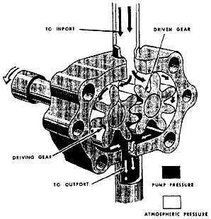
Power-Driven Pumps As previously mentioned, power pumps are generally driven by the aircraft engine, but may also be electric-motor driven. Power pumps are classified according to the type of pumping action used, and may be either the gear type or piston type. Power pumps may be further classified as constant displacement or variable displacement. A constant displacement pump is one that displaces or delivers a constant fluid output for any rotational speed. For example, a pump might be designed to deliver 3 gallons of fluid per minute at a speed of 2,800 revolutions per minute. As long as it runs at that speed, it will continue to deliver at that rate, regardless of the pressure in the system. For this reason, when the constant displacement pump is used in a system, a pressure regulator or unloading valve must also be incorporated. The pressure regulator valve will maintain a set pressure in the system by diverting excess pump flow back to the reservoir. The unloading valve will divert all pump flow back to the reservoir when the preset system pressure is reached. This condition remains in effect until further demand is placed on the system. A variable displacement pump has a fluid output that varies to meet the demand of the system. For example, a pump might be designed to maintain system pressure at 3,000 psi by varying its fluid output from 0 to 7 gallons per minute. When this type of pump is used, no external pressure regulator or unloading valve is needed. This function is incorporated in the pump and controls the pumping action by maintaining a variable volume, at near constant pressure, to meet the hydraulic system demands. GEAR-TYPE PUMP. A gear-type pump consists of two meshed gears that revolve in a housing (fig. 7-14). The drive gear in the installation is turned by a drive shaft that engages an electric motor. The clearance between the gear teeth as they mesh and between the teeth and pump housing is very small. The inlet port is connected to the reservoir line, and the outlet port is connected to the pressure line. In the illustration, the drive gear is turning in a counterclockwise direction, and the driven (idle) gear is turning in a clockwise direction. As the teeth pass the inlet port, fluid is trapped between the teeth and the housing. This fluid is carried around the housing to the outlet port. As the teeth mesh again, the fluid
between the teeth is displaced into the outlet port. This action produces a positive flow of fluid under pressure into the pressure line. A shear pin or shear section that will break under excessive loads is incorporated in the drive shaft. This is to protect the engine accessory drive if pump failure is caused by excessive load or jamming of parts. All gear-type pumps are constant displacement pumps. These pumps are usually driven by a dc wound electric motor. For those aircraft using batteries, the pump may be used to build up hydraulic pressure for the brake system during towing operation. Maintenance of a pump at the organizational level consists of replacement of the complete assembly. The motor and pump may be ordered separately; however, this is normally done by intermediate- and depot-level maintenance only. Removal and installation procedures are found in the applicable MIM. The following removal procedures are typical examples. 1. Relieve reservoir pressure. 2. Pull the pump circuit breaker and place a warning card, DO NOT OPERATE, on the pump switch. 3. Disconnect the pump motor electrical connection at the motor. 4. Drain the pump reservoir or cap the reservoir suction line. 5. Disconnect the drain line at the pump. 6. Loosen the pressure and suction lines "B" nuts. 7. Remove the mounting screws/bolts that secure the pump assembly to the aircraft structure. 8. Disconnect completely the pressure and reservoir suction lines at the pump. 9. Cap all open lines, and lift the pump assembly out of the aircraft. The following installation procedures are typical examples: 1. Place the pump on the aircraft structure mounting pad. Connect the pressure and suction lines to the pump ports and tighten the "B" nuts fingertight. 2. Align and install the mounting screws/bolts. 3. Tighten the "B" nuts to the correct torque values. 4. Attach the electrical connection to the motor. 5. Service the reservoir to the proper level. 6. Perform operational check according to the applicable MIM. NOTE: Prior to the installation of hydraulic units, the preservation fluid must be drained and the unit flushed with clean hydraulic fluid. |
 
|
|
|
|
|
Integrated Publishing, Inc. - A (SDVOSB) Service Disabled Veteran Owned Small Business
|