Custom Search
|
|
  |
|
|
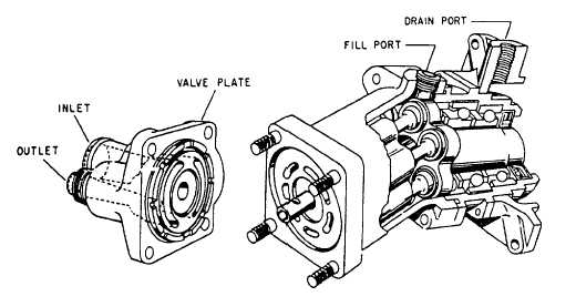
PISTON-TYPE PUMP (CONSTANT DIS-PLACEMENT).
Piston-type
constant displace-ment pumps
consist of a circular cylinder block with either
seven or nine equally spaced pistons. Figure 7-15
is a partial cutaway view of a seven-piston pump manufactured
by Vickers, Incorporated.
The main parts of the pump are the drive shaft, pistons, cylinder block, and valve plate. There are two ports in the valve plate. These ports connect directly to openings in the face of the cylinder block. Hydraulic fluid is sucked in one port and forced out the other port by the reciprocating (back-and-forth) motion of the pistons. There is a fill port in the top of the cylinder housing. This opening is normally kept plugged, but it can be opened for testing the pressure in the housing or case. When you install a new pump or newly repaired one, this plug must be removed and the housing filled with fluid before the pump is operated. There is a drain port in the mounting flange to drain away any leakage from the drive shaft oil seal. When the drive shaft is rotated, it rotates the pistons and cylinder block with it. The offset position of the cylinder block causes the pistons to move back and forth in the cylinder block while the shaft, pistons, and cylinder block rotate together. As the pistons move back and forth in the cylinder block, they draw the fluid in one port and force it out the other. This action creates a steady, nonpulsating flow of fluid. Certain models of this pump are capable of developing up to 3,000 psi working pressure. Constant displacement pumps of this series are designed so they can be driven in either direction. The direction of rotation of the pump must coincide with the engine accessory section. The pump rotation can be determined by referring to an arrow on the pump housing adjacent to the valve plate. The only change necessary when changing the direction of rotation of the pump is to rotate the valve plate 180 degrees. Before installation, the pump mounting flange and shim, if used, must be wiped clean. The pump must be primed by filling the housing with hydraulic fluid through the fill port. The exposed drive shaft spline should be lubricated. To ensure internal cleanliness, the shipping plugs should not be removed until the lines are ready for attachment. Normally, for repair, the pump should be shipped to an intermediate-level activity; however, replacement of packings and gaskets can be accomplished in the field. To prevent damage in the event of the pump binding, a shear section is incorporated in the drive shaft coupling. The coupling may be replaced if the cause of the shearing is known and has been remedied. Immediately after removal, the pump housing should be filled two-thirds full with hydraulic fluid; the drive shaft couplings should be suitably protected by a wood block; and the ports securely plugged to prevent the entrance of foreign matter. PISTON-TYPE PUMPS (STRATOPOWER VARIABLE DISPLACEMENT). There are several models of the Stratopower variable displacement pump currently used on naval aircraft; however, all are similar in principle of operation, The pump described here is a Model 65 WB06006, rated at 3,000 psi and capable of delivering 13 gallons of fluid per minute at 3,800 rpm. Pressure regulation and flow control are accomplished internally, automatically adjusting pump delivery to meet the system demands. Flow cutoff begins at approximately 2,850 psi, and it reaches zero (unloads) at 3,000 psi. When the pump is operating in the unloaded condition, the bypass system provides circulation of fluid internally for cooling and lubrication of the pump. The pump has three portsthe suction port, the discharge port, and the drain or bypass port. The latter port is connected to the reservoir return line. The pump is driven from the engine accessory drive by a splined drive coupling. A shear section is provided in the pump drive shaft to prevent damage from overload. Figure 7-16 shows the internal features of the pump. Four major functions are performed by the internal parts of the pump. These functions are mechanical drive, fluid displacement, pressure control, and bypass. |
 
|
|
|
|
|
Integrated Publishing, Inc. - A (SDVOSB) Service Disabled Veteran Owned Small Business
|