Custom Search
|
|
  |
|
|
Cable Control Systems Cables have many advantages. They will not sever readily under sudden strains. Cables are stronger than steel rods or tubing of the same size. They flex without setting (permanent deformation) and can be led easily around obstacles by using pulleys. Cables can be installed over long distances (such as in large aircraft) without a great degree of sagging or bending. Vibration will not cause them to harden, crystallize, or break, as may be the case with push-pull control rods. Because of the great number of wires used in cables, cable failure is never abrupt, but is progressive over periods of extended use. When used for the manipulation of a unit in a control system, they are usually worked in pairs-one cable to move the unit in one direction, the other to move it in the opposite direction. Weight is saved in spite of a second cable because the push-pull rod needed to cause a similar movement in a unit would have to be quite thick and heavy (comparatively speaking). Since cables are used in pairs and are stretched taut, very little play is present in system controls, and no lost motion exists between the actuating device and the unit. Consequently, cable-controlled units respond quickly and accurately to cockpit control movement. In some simple cable systems, only one cable is used, and a spring provides the return action.
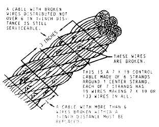
CABLE MAINTENANCE. Cable control systems require more maintenance than rigid linkage systems; therefore, they must be inspected more thoroughly. Cables must be kept clean and inspected periodically for broken wires, corrosion, kinking, and excessive wear. Broken wires are most apt to occur in lengths of cable that pass over pulleys or through fairleads. On certain periodic inspections, cables are checked for broken wires by passing a cloth along the length of the cable. Where the cloth snags the cable is an indication of one or more broken wires. WARNING Your bare hands should NEVER be used to check for broken wires. Using your bare hands to check for broken wires could result in personal injury. Tests have proven that control cables may have broken wires and still be capable of carrying their designated load. However, any 7 x 19 cable that shows more than six broken wires in any 1-inch length, or any 7 x 7 cable that shows more than three broken wires in any 1-inch length, must be replaced. A maximum of three broken wires per inch is allowable in the length of cables passing over pulleys, drums, or through fairleads. Figure 9-20 shows how to determine if a cable is serviceable. Corrosion, kinking, and excessive wear should be given particular attention during cable inspection. If a cable is found to be kinked or badly worn, it should
NOTE: Do not use metal wool or solvents to clean installed cable. Metal wool will embed tiny dissimilar metal particles and create further corrosion problems. The use of solvents will remove the internal cable lubricant and allow the cable strands to abrade and further corrode. When a cable is found to be unserviceable and a spare cable is not available, an exact duplicate of the damaged cable may be prepared. This will involve cutting a length of cable to the proper length, attaching the necessary end fittings, and testing the assembly. To determine the proper length to which the new cable will be cut, you should first determine the overall length of the finished cable assembly. This may be accomplished by measuring the old cable assembly or by reading the measurements provided in the MIM for the aircraft concerned. Replacing cables in the aircraft, especially those routed through inaccessible spaces, can be difficult. One method is to secure a snaking line to the cable to be replaced, remove the pulleys from the brackets, and pull out the old cable while pulling the snaking line into the cable system run at the same time. Attach the new cable assembly to the snaking line, and pull the snaking line out to pull the new assembly into place. Replace the pulleys and attach the new cable in the system. |
 
|
|
|
|
|
Integrated Publishing, Inc. - A (SDVOSB) Service Disabled Veteran Owned Small Business
|