Custom Search
|
|
  |
|
|
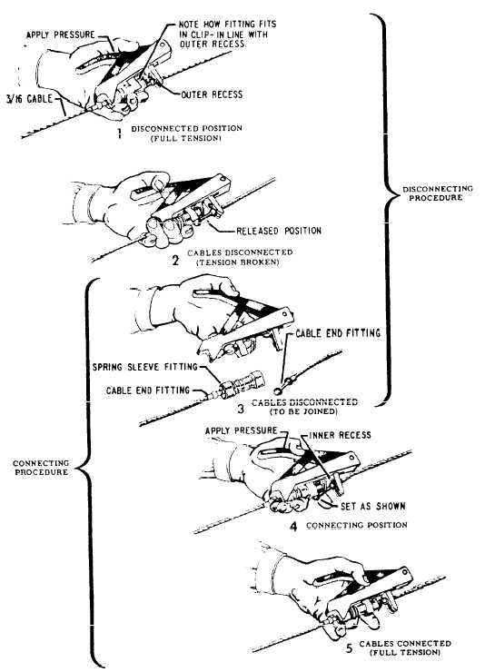
QUICK DISCONNECTS. Quick
disconnects are used in cable
systems that may require frequent disconnecting.
One type of quick disconnect is made with
steel balls swaged to the ends of the cable, slipped
into a slotted bar, and secured with spring-loaded
sleeves on each end of the bar. Figure
9-21 shows the procedures for disconnecting and
connecting this type of quick-disconnect fitting. Rigid Control Systems Rigid control systems transfer useful movement through a system of push-pull rods, bell cranks, walking beams, idler arms, and bungees. The simplest rigid control system may consist of push-pull rods and bell cranks only. PUSH-PULL RODS. Push-pull rods are rigid tubes equipped with eye fittings at each end or with a clevis fitting at one end and an eye fitting at the other
Push-pull rod linkage must be inspected closely for dents, cracks, and bent tubing. Damaged tubes may have to be replaced. End fittings are checked for damage, wear, and security of attachment. Worn or loose fittings must be replaced. When you are replacing a damaged push-pull tube, the correct length of the new tube may be obtained by loosening the check nut and turning the end fitting in or out, as necessary. When the push-pull tube has been adjusted to its correct length, the check nut must be tightened against the shoulder of the end fitting. Normally, only one end of a push-pull rod is adjustable. The adjustable end has a hole (witness hole) drilled in the rod. The hole is located at the maximum distance the base of the end fitting is allowed to be extended. If the threads of the end fitting can be seen through this hole, the end fitting is within safe limits. When you are attaching push-pull rods with ball bearing end fittings, the attaching bolt and nut must tightly clamp the inner race of the bearing to the bell crank, idler arm, or other supporting structure. Nuts should be tightened to the torque values listed in the aircraft MIM. After installing a new push-pull rod in a flight control system, the control surface must be checked for correct travel. Procedures for accomplishing this are described later in this chapter. If the travel is incorrect, the length of the push-pull fod must be readjusted. |
|
|
|