Custom Search
|
|
  |
|
|
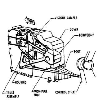
Elevator Control System The elevator control system, shown in figure 9-2, is typical of many conventional elevator systems. It operates by the control stick in the cockpit and is hydraulically powered. The operation of the elevator control system starts when the control stick is moved fore or aft. The movement of the stick transfers through the control cables to move the elevator control bell crank. The bell crank transmits the movement to the hydraulic actuating cylinder through the control linkage. The hydraulic actuating cylinder operates a push-pull tube, which deflects the elevators up or down. The elevator system uses forward and aft bobweights. The bobweights induce a load on the control stick during pitching and vertical acceleration and prevent pilot-induced oscillations through the elevator controls. If the gravity force is increased on the bobweights, the induced load tends to return the control stick to the neutral position. Viscous dampers on the bobweight assemblies retard control stick movement to prevent overcontrol. Overcontrol could cause airframe overstress. The elevator forward bobweight serves to help recenter the control stick when a heavy gravity load pulls against the airframe. The forward bobweight and damper assembly is in a housing forward of the control stick in the cockpit. See figure 9-3. The
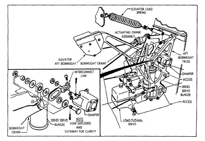
Figure 9-3.Elevator forward bobweight and damper assembly. assembly consists of a bobweight, a viscous damper, and a push-pull tube. The push-pull tube is the interconnect between the control stick and the bobweight. The damper is located at the pivot point of the bobweight and restricts fast movement of the bobweight. The aft bobweight and damper assembly works with the forward assembly to overcome the heavy pull of gravity and retard the chance of overcontrol. See figure 9-4. This assembly is installed in the fuselage, forward and below the horizontal stabilizer. It connects to the elevator control cables. The aft assembly consists of a bobweight, a viscous damper, and a load spring. The bobweight connects to the elevator control bell crank and the damper. The load spring is between the elevator control bell crank and the fin structure to balance the forward and aft bobweights when the elevator is in a neutral position. The elevator power mechanism changes the mechanical movement of the control stick to the hydraulic operation of the elevator. See figure 9-5. The mechanism is in the aft section of the aircraft directly below the horizontal stabilizer. As in the aileron power system, the mechanism consists of a hydraulic power cylinder, control valves, linkage, and hydraulic piping. When the elevator controls are operated, the control valves port hydraulic pressure to the power cylinder. The hydraulic pressure extends or retracts the cylinder piston to move the push-pull tubes. The push-pull tubes deflect the elevators. The control valves are two separate valves connected in tandem by linkage. One valve is supplied hydraulic pressure by the utility hydraulic system. The other valve is supplied hydraulic pressure by the flight control hydraulic system. The power cylinder has dual hydraulic chambers to work from each control valve. Each hydraulic system simultaneously supplies
The load-feel bungee, shown in figure 9-5, provides an artificial feel to the control stick. The bungee acts as a centering device for the elevator system. Control stick movement compresses the spring in the bungee. Releasing the control stick causes the compressed spring to return the stick to neutral. The bungee also adds a gearing effect between the horizontal stabilizer and the elevators. When the stabilizer is trimmed to give an aircraft nose up condition, the bungee action adds nose up elevator. With the stabilizer trimmed nose down, the bungee action adds nose down attitude on the elevator. |
 
|
|
|
|
|
Integrated Publishing, Inc. - A (SDVOSB) Service Disabled Veteran Owned Small Business
|