Custom Search
|
|
  |
|
|
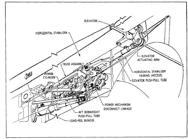
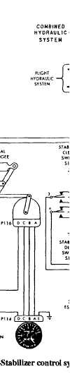
Horizontal Stabilizer Control System (Single
Axis) Various aircraft manufacturers identify the horizontal stabilizer control system by different names. On one aircraft, it is called a unit horizontal tail (UHT) control system. On another aircraft, it is called the stabilizer control system. Regardless of the variation in nomenclature, these systems function to control the aircraft pitch about its lateral axis.
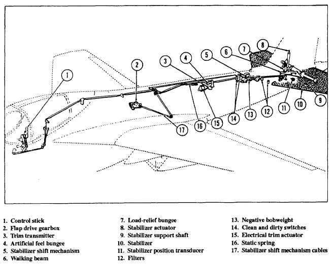
Pilot signals are conveyed through bell cranks and pushrods and a trim mechanism to the input linkage of the stabilizer actuator. A trim switch on the control stick grip provides a means of setting stabilizer trim. Stabilizer trim is displayed by the stabilizer trim indicator located on the pilots lower instrument panel. See figure 9-7.
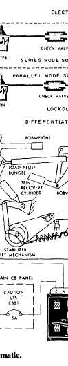
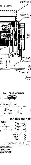
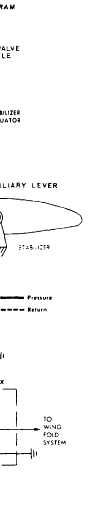
The position of the stabilizer is shown on the integrated position indicator located on the left side of the pilots instrument panel. When the stabilizer is in the "clean" configuration, the STAB window of the indicator shows the word CLEAN. When the stabilizer is in the "dirty" configuration, the window shows a picture of a stabilizer.The stabilizer actuator (fig. 9-7) is a tandem-type actuator powered by both flight and combined system pressures. It contains a power valve shuttle, two tandem-mounted power pistons, a servo ram, an electrohydraulic servo valve, a lockout actuator, and parallel and series mode solenoid valves. The actuator can operate in any of three modes-manual, series, or parallel. Refer to figure 9-7 to help you understand the three modes of operation, as described in the following paragraphs. |
|
|
|