Custom Search
|
|
  |
|
|
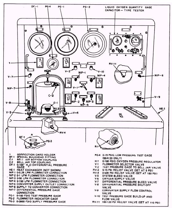
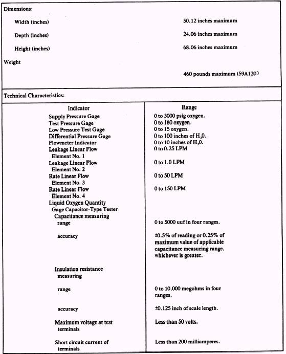
CHAPTER 1 LIQUID OXYGEN CONVERTER TEST STAND 59A120 The PRs perform an enormous amount of testing of oxygen components. Although lower rated personnel perform much of this work, the responsibility for maintaining liquid oxygen converter test stands in top running condition is that of the senior PR. Knowing the functions, daily inspections, and adjustments required to maintain such equipment is essential for the lower rated PRs. This information can be found in the Aircrew Survival Equipmentman 3 & 2, Vol 2. However, determining the causes of malfunctions, making major adjustments, and replacing parts are the responsibilities of the First Class and Chief Petty Officer. This chapter covers the 59A120 Liquid Oxygen Converter test stand shown in figure 1-1. THE 59A120 TEST STAND The 59A120 is designed to test all liquid oxygen converters and rigid seat survival kits (RSSK) components used-in today's naval aircraft. All instruments, mechanisms, and equipment of the test stand are designed to meet certain criteria. They are designed to meet this criteria even when subjected to the normal pitch . and roll of a ship. The test stand is comprised of a differential pressure gage; three pressure gages; four linear flow elements; a liquid oxygen quantity gage capacitor-type tester; a flowmeter indicator; a bell jar; a heat exchanger; and the necessary integral piping, wiring, hoses, and valves to properly test oxygen components. The performance and technical characteristics of the test stand are shown in table 1-1. The 59A120 test stand tests liquid oxygen converters, components, and RSSK components for leaks, flow settings, and quantity gaging. This test stand is designed to test liquid oxygen converter components and accessories to make sure they work properly. The test stand is used to perform periodic preventive maintenance, tests, and adjustments. PREPARATION FOR USE Preparing the test stand for use is divided into five separate tasks to be done by the PR or by the on-site metrology calibration team (CAL TEAM). The five tasks and responsible personnel are as follows: 1. Installation\PR 2. Visual Inspection\PR 3. Correction card preparation-CAL TEAM 4. Leakage testing\PR 5. Calibration\CAL TEAM Procedures for installation, visual inspections, and leakage testing of the 59A120 are done following NAVAIR 13-1-6.4. Procedures for leakage testing are discussed in this chapter; however, they are not to be used in place of the aforesaid NAVAIR manual. One of the keys to a trouble-free test stand is the performance of periodic inspections on the test stand. By performing the periodic inspections on time, you find troublesome areas before they become problems.
Figure 1-1.\Liquid Oxygen Converter Test Stand ControI Pad and Counter Top.
Table 1-1.\Leading Particulars
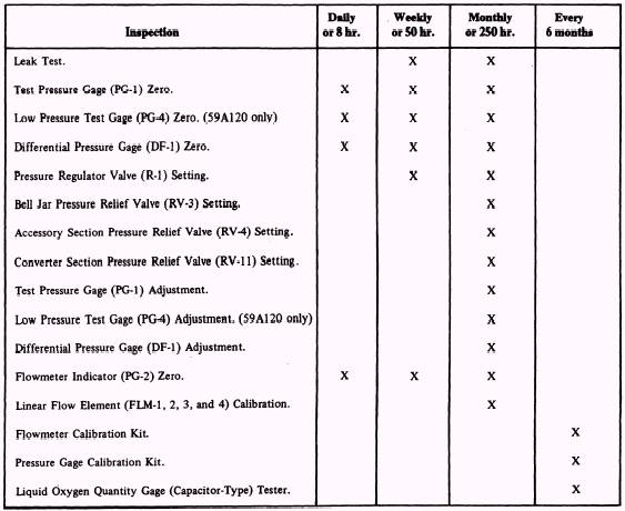
Table 1-2 lists, by calendar and operating time, the periodic inspections to be performed in the interest of efficient operation. CLEANING A clean test stand not only looks neat but it gives better service. A clean stand is essential if leaks are to be located in a timely manner. All external parts of the test stand must be cleaned with oxygen systems cleaning compound Mil-C-81302, Type 1. When you clean the test stand, be sure the test adapters and connection hoses stored in the accessory tray are also cleaned. If the front panel of the test stand must be removed for any reason, you must ensure that all gage tester surfaces are free from dust and any other foreign matter. The best way to clean these surfaces is to use clean, low-pressure dry air (about 10 psi is recommended). To clean the interconnecting piping, hoses, and fittings on the test stand, you should use clean, dry air pressure not to exceed 160 psig. Type 1 Freon is recommended for cleaning the terminals of the Liquid Oxygen Quantity Gage Tester (capacitor type) test stand. The bell jar on the 59A120 test stand has a sealing O-ring. This O-ring must be cleaned with distilled water and lubricated with alight coat of lubricant Mil G 27617. Table 1-2.\Periodic Inspection Chart WARNING Never apply oil, grease, or any other material not approved for use in the presence of gaseous and liquid oxygen systems. |
 
|
|
|