Custom Search
|
|
  |
|
|
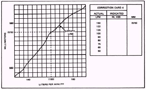
CORRECTION CARD PREPARATION AND CALIBRATION An on-site CAL TEAM must prepare the correction cards and calibrate the 59A120 following NAVAIR 13-1-6.4 procedures. However, because of the operational commitments of today's Navy, you may find yourself with a test stand that needs calibration and correction card corrections when CAL TEAM services are not available. This chapter covers the procedures outlined in the NAVAIR 17-15BC-20 for correction card preparation and calibration. NOTE: This RTM does not authorize you to calibrate the test stand nor does it authorize you to make correction card corrections. These tasks must be authorized by higher authority. CORRECTION CARDS Before you operate the 59A120 test stand, individual correction cards for the following components must be prepared: DF-1, PG-1, PG-4, FLM-1, FLM-2, FLM-3, and FLM-4. These correction cards must be prepared prior to calibration of the 59A120 test stand. To perform calibration and to prepare correction cards, you will need the Flowmeter Calibration Kit and the four graphs that are supplied with the kit for that particular test stand. Each kit will be serialized with the same number as the serial number of the test stand. To prepare the cards, convert the actual liter-per-minute (lpm) flows to indicated millimeter (mm) flows on cards 4, 5, 6, and 7. Refer to figure 1-2 in the following steps: 1. Using the applicable graph for the flowmeter selected, locate the desired lpm at the bottom of the graph. 2. Trace the selected lpm lineup to where it intersects the graph line. 3. Trace the line from point of intersection to the left-hand edge of the graph to determine mm. Enter this figure in the appropriate column of the correction card.
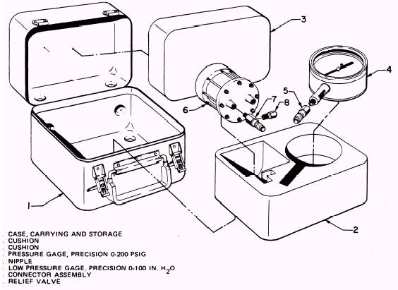
Figure 1-2.\Conversion Example. 4. Using applicable graphs, repeat steps 1 through 3 for all actual flows given on correction cards 4 through 7. 5. Indicated flows (in. H2O) are entered on the cards when you calibrate the test stand. Differential Pressure Gage (DF-1) To prepare the differential pressure gage (DF-1) correction card, refer to figure 1-1 in the following steps: 1. Close system bleed valve V-5 and open the oxygen supply cylinder valve. Connect precision-0-to-100-in. H 2O low-pressure gage 6 (figure 1-3) to bell jar bottom coupling C-1. Open differential pressure shutoff valve V-8. NOTE: Correction cards will be completed at this time. 2. Slowly open oxygen supply valve V-6 O is indicated on the precision-0-to-100-in. H 2O low-pressure gage. until 100 in. H2 Compare this gage with the reading displayed on differential pressure gage DF-1. 3. Enter the difference (if any) in the indicated in. H2 O column of correction card number 1. 4. Slowly open system bleed valve V-5 to reduce the pressure indication on the precision-0-to-100-in. H 2O low-pressure gage. Reduce pressure in 20-in. H2O increments. Enter the corrective differential (if any) at each interval on the correction card. 5. When all entries have been made on the correction card, close oxygen supply valve V-6 and differential pressure shutoff valve V-8. 6. Open system bleed valve V-5 and bleed the low-pressure gage. system. Disconnect the precision-0-to-100-in. H2O Test Pressure Gage (PG-1) To prepare the test pressure gage (PG-1) correction card, proceed as follows: 1. Connect precision-0-to-200-psig pressure gage 4 (figure 1-3) to bell jar bottom coupling C-1.
Figure 1-3.\Pressure Gage Calibration Kit. Close system bleed valve V-5, and open test pressure gage to bell jar valve V-2. 2. Open oxygen supply valve V-6 until 160 psig registers on the precision-0-to-200-psig pressure gage; then close valve V-6. 3. Compare the precision-0-to-200-psig pressure gage reading with pressure registered on test pressure gage PG-1. Enter the corrective differential (if any) in the indicated psig column of test stand correction card number 2. 4. Slowly open system bleed valve V-5 to reduce the pressure registered on the precision-0-to-200-psig pressure gage. Enter the corrective differential (if any) at each specified pressure on the test stand correction card. 5. After all correction card entries have been completed, close system bleed valve V-5 and oxygen supply valve V-6. |
 
|
|
|