Custom Search
|
|
  |
|
|
Low-Pressure Test Gage (PG-4) To prepare a low-pressure test gage (PG-4) correction card, proceed as follows: 1. With precision-0-to-200-psig test gage 4 (figure 1-3) still attached to bell jar bottom coupling C-1, open oxygen supply valve V-6 until 7.5 psig is indicated on the precision-0to-200-psig test gage. The pointer of low-pressure test gage PG-4 should be at midscale. If the pointer is not at midscale, adjust by turning the adjustment screw on the back of the gage. 2. Slowly open oxygen supply valve V-6 until 14 psig registers on the precision-0-to-200psig test gage; then close oxygen supply valve V-6. Compare the reading with the indication on low-pressure test gage PG-4. Enter the corrective differential (if any) in the indicated psig column of test stand correction card number 3. 3. Slowly open system bleed valve V-5 and reduce the pressure indicated on the precision-0-to-200-psig pressure test gage in 2-psig increments. At each increment, enter the corrective differential (if any) on the test stand correction card. 4. After all correction card entries have been completed, ensure oxygen supply valve V-6 is closed; then open system bleed valve V-5 and close test-pressure-gage-to-bell-jar valve V-2. Remove the precision-0-to-200-psig test gage from bell jar base coupling C-1. . Linear Flow Elements (FLM-4), (FLM-3), (FLM-2), and (FLM-1) To prepare the linear flow element correction cards, place the Flowmeter Calibration Kit (shown in figure 1-4) on the test stand counter top; then
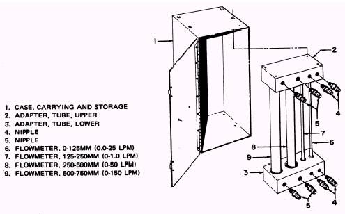
Figure 1-4.\Flowmeter Calibration Kit. 1-7 beginning with the 0-to-150-lpm flow element (FLM-4), proceed as follows: 1. Using hose assembly 3 (figure 1-5), connect the top connection of the 500-to-750-mm calibration kit flowmeter 9 (figure 4-4) to test stand flow element connection NIP-4. Using hose assembly 6 (figure 1-5), connect the bottom connection of the calibration kit flowmeter to bell jar base coupling C-1. 2. Set flowmeter selector valve V-1 to the 0-to-150-lpm position. Ensure system bleed valve V-5 is closed. NOTE: Flows used shall be taken from the mm column of the calibration correction cards. This previously completed column contains flows in millimeters (mm) equivalent to corresponding lpm flows. 3. Using oxygen supply valve V-6, set the flow equivalent to 150 lpm (from correction card number 4) on the 500-to-750-mm calibration kit flow element. The flow, in inches H 2O, will be displayed on flowmeter indicator PG-2. Enter this reading in the indicated in. H 2O column of correction card number 4 opposite the actual mm flow being drawn. 4. Reduce the flow to the next millimeter reading by adjusting oxygen supply valve V-6. Repeat step 3. Continue in this manner until all flows on correction card number 4 have been completed. 5. Close oxygen supply valve V-6 and disconnect the hose and the calibration kit flowmeter from the test stand. NOTE: Hose assembly 3 (figure 1-5) and hose assembly 6 are used in calibrating all linear flow elements. 6. Connect the top connection of the 250-to-500-mm calibration kit flowmeter to test stand flow element connection NIP-3; connect the bottom connection to bell jar base coupling C-1. Rotate flowmeter selector valve V-1 to the 0-to-50-lpm position. Ensure system bleed valve V-5 is closed. 7. Repeat procedures outlined in steps 3 through 5, using flows given on correction card number 5. 8. Connect the top connection of the 125-to-250-mm calibration kit flowmeter to test stand flow element connection NIP-2; connect the bottom connection to bell jar coupling C-1. Rotate flowmeter selector valve V-1 to the 0-to-1.0-lpm position. Ensure system bleed valve V-5 is closed. 9. Repeat procedures outlined in steps 3 through 5, using flows given on correction card number 6. 10. Connect the top connection of the 0-to-125-mm calibration kit flowmeter to test stand flow element connection NIP-1; connect the bottom connection to bell jar base coupling C-1. Rotate flowmeter selector valve V-1 to the 0.0-to-0.25-lpm position. Ensure system bleed valve V-5 is closed. 11. Repeat procedures outlined in steps 3 through 5, using flows given on correction card number 7. 12. Disconnect hoses 3 and 6 (figure 1-5) from the calibration kit and test stand. Close oxygen supply cylinder valve V-6 and open system bleed valve V-5 to bleed the test stand. Secure all test stand valves. TROUBLESHOOTING A properly working test stand will give you outstanding results while testing oxygen converters. As with any test stand, a small leak in your plumbing system will give you inaccurate readings and may cause you to think you have a defective converter or component. Some parts on the 59A120 test stand must be corrected when they become defective by the on-site meteorology calibration team. You might have a gage that has a pointer which isn't zeroed, or you might have a flow element that consistently reads low. You could also have a gage that provides correct readings over only part of the scale. In such cases, you will need the calibration team's assistance to repair the component. Upon completion of any maintenance action, you will be required to fill out a Ground Support Equipment Subcustody and Periodic Maintenance Record (OPNAV 4790/50) and a Ground Support Equipment Custody and Maintenance Record (OPNAV 4790/51). The following problems may occur within your test stand; you, as a senior PR, will be required to fix them. Refer to NAVAIR 17-15BC-20 for parts removal and replacement. |
 
|
|
|