Custom Search
|
|
  |
|
|
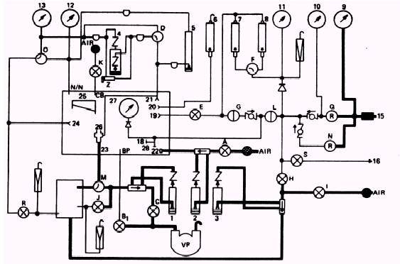
ALTITUDE SENSING SYSTEM This system (figure 2-9) senses the pressure (less 1 atmosphere) in the altitude chamber or suit simulator tank. In this case, we refer to atmosphere as a unit of pressure equal to 14.69 pounds per square inch. Both the high-range and lowrange altimeters are operated by differential pressure. The high-range altimeter (12) senses the altitude inside the chamber through the chamber reference port (N/N). When you place the pressure selector valve (O) in the ALTITUDE CHAMBER position, the low-range altimeter senses the altitude through the same chamber reference port (N/N). The low-range altimeter also senses the pressure inside the suit simulator tank. You must place the reference pressure selector valve (O) in the SUIT SIMULATOR position and open the suit simulator reference shutoff valve (R) for the low-range altimeter to read this pressure. PRESSURIZING THE ALTITUDE SENSING SYSTEM When you pressurize the altitude sensing system, be sure the reference pressure selector valve (O) is in the ALTITUDE CHAMBER position and open the vacuum control valve (Bl). When you open the control valve (Bl), ascend to 50,000 feet. The altitude will be indicated on the high-range altimeter (12). Stabilize with control valve B1 at this altitude and check for leaks. Open chamber bleed valve (K) and return to sea level. Close valve (K) when you reach sea level. If you find that the test stand has no leaks at this point, turn the reference pressure selector valve (O) to the SUIT SIMULATOR position; then open the suit simulator reference shutoff valve (R) fully. Place the flow selector valve (M) in the SUIT SIMULA-TOR position. Now you are ready to ascend to altitude. Open the vacuum control valve (Bl) and ascend to 35,000 feet. This altitude will be indicated on the low-range altimeter (13). Again stabilize with control valve (B1) and check for leaks. Close the vacuum control valve (B l) and return to sea level. To setup the test stand for the chamber bleed system test, close the chamber bleed valve (K). Place the reference pressure selector valve (O) in the ALTITUDE CHAMBER position; close the suit simulator shutoff valve (R) and place the flow selector valve (M) in the REGULATOR position. Leave all valves and connections in their present position. CHAMBER BLEED SYSTEM The chamber bleed system shown in figure 2-10 is a very simple system used to introduce a large volume of air into the altitude chamber. When you open the chamber bleed valve (K), ambient air flows into the chamber through the chamber bleed port (CB). The altitude in the chamber drops until the pressure inside the chamber equalizes with the pressure at sea level. PRESSURIZING THE CHAMBER BLEED SYSTEM Open the vacuum control valve (B1) and ascend to 10,000 feet; then close the valve to stabilize your altitude. A drop in altitude on the low-range altimeter (13) indicates a leak. If there is no drop in altitude, open the chamber bleed valve (K) and descend to sea level. When you reach sea level, close the chamber bleed valve (K). The test stand is now ready to test the flow measuring system. FLOW MEASURING SYSTEM This system is the largest and most important system on the test stand. The purpose of the flow measuring system is to measure flows of air, nitrogen, or air/nitrogen mixture from an item under test. As you can see in figure 2-11, the system consists of vol-o-flow elements, flow indicating manometers, control valves, and selector valves. The flow measuring system is made up of the output, input, and vent flow subsystems. The different subsystems function with the vacuum running. Output The output flow system originates at the piezometer (26) and flows through the output port (23) to the flow selector valve (M). It is then directed to either the output vol-o-flow element or the suit simulator tank. When the flow selector valve (M) is placed in the REGULATOR position, the flow is directed to the output vol-o-flow element. The volume of flow is controlled by the output valve (C) and is indicated on the output flow manometer (l). The only time this system is used with the flow selector valve (M) in the SUIT SIMULATOR position is when the full pressure suit breathing regulator is tested.
Figure 2-11.\Model 1172AS100 flow measuring system. Input The input flow system can only be used with the chamber at altitude. This system originates at the air intake on the face of the test stand. When the input valve (A) is opened, ambient air flows through this valve (A) to the input vol-o-flow element. It then flows through the input flow manometer (2) to the input port (22) inside the chamber. You can control this flow by opening or closing the input valve (A). |
 
|
|
|
|
|
Integrated Publishing, Inc. - A (SDVOSB) Service Disabled Veteran Owned Small Business
|