Custom Search
|
|
  |
|
|
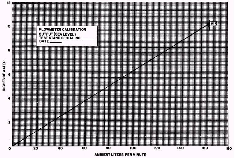
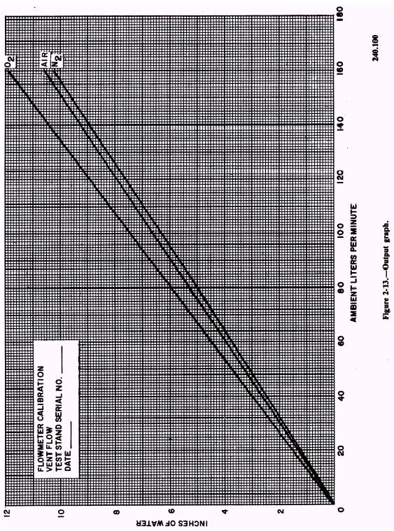
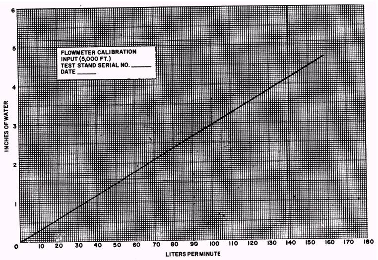
VENT FLOW SYSTEM The vent flow system can originate at either the vent ambient valve (I) or the vent pressure valve (H). Normally, the vent pressure valve (H) is used only when the chamber and suit simulator tank are at sea level. The vent ambient valve (I) can only be used at altitude. When the vent ambient valve (I) is used, air is admitted through an intake port in the rear of the test stand. It then flows through the vent flow vol-o-flow element and is indicated on the vent flow manometer (3). The air then flows to the suit simulator tank. When the flow selector valve (M) is in the SUIT SIMULATOR position, air flows to the output port (23) inside the chamber and continues to the piezometer (26). You may also direct air from the suit simulator tank to the output vol-o-flow element and the output flow manometer (1) by opening the flutter dampener valve (J). The vent pressure valve (H) is used only with low-pressure nitrogen. To use the flow measuring system, you must convert the actual liter-per-minute (lpm) flows to indicated in. H2O. You accomplish this with the aid of the input, output, and vent flow graphs supplied with the test stand. See figures 2-12, 2-13, and 2-14. The actual lpm is found at the bottom of the graph. Follow the selected lpm line up to the point where it intersects the air or nitrogen line. From the point of intersection, follow the lpm line to the left-hand side of the graph and determine in. H2O . PRESSURIZING THE FLOW MEASURING SYSTEM Before you start pressurizing the flow measuring system, use the 10,000-foot altitude air line on the input and output graph to convert 100 lpm to in. H2O. Open the vacuum control valve (Bl), ascend to 10,000 feet, and then close the valve ( Bl). Open the output valve (C)to the in. H2O equivalent of 100 lpm. This flow will be indicated on the output-flow manometer (l). Now, open the input valve (A) to the in. H2O equivalent of 100 lpm; this flow will be indicated on the input-flow manometer (2). Close valves C and A before you check for leaks. If the system has no leaks, use the bleed valve (K) and return to sea level. Use the nitrogen line on the vent flow graph and convert 150 lpm to in. H2O . Use the low-pressure regulator to apply 70 psi. Place the flow selector valve (M) in the SUIT SIMULATOR position. Open the vent pressure valve (H) very slowly to the in. H2O equivalent of 150 lpm. This will be indicated on the vent flow manometer (3). Now close the vent pressure valve (H). At this time you should convert 150/lpm to in. H2O using the air line on the vent flow graph. Place the reference selector valve (O) in the SUIT SIMULATOR position. Now open the suit simulator reference shutoff valve (R) fully and place the flow selector valve (M) in the SUIT SIMULATOR position. Open the vacuum control valve (Bl) and ascend to 35,000 feet. Now close down the valve ( Bl) to stabilize the altitude at the same time you are opening the vent ambient valve (I) to the equivalent of 150 lpm. This flow will be indicated on the vent flow manometer (3). Now close the vent ambient valve (I) and the vacuum control valve (Bl). Secure the test stand as outlined in NAVAIR 13-1-6.4. This completes the tests for the nine different systems. If all the systems checked out, the test stand will give you outstanding service. Page 2-14.
Figure 2-12.\Input graph.
Figure 2-13.
Figure 2-14.\Vent flow graph. |
 
|
|
|
|
|
Integrated Publishing, Inc. - A (SDVOSB) Service Disabled Veteran Owned Small Business
|