Custom Search
|
|
  |
|
|
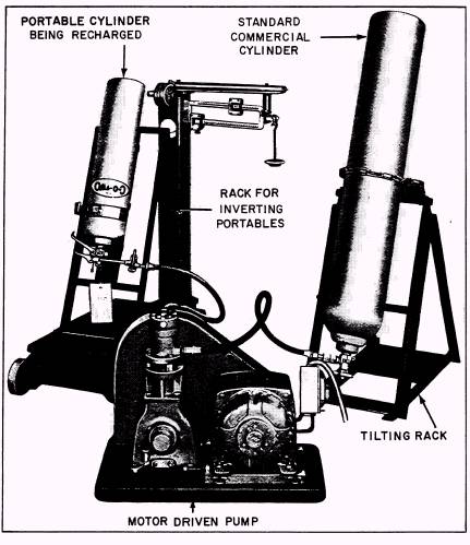
CHAPTER 3 CARBON DIOXIDE TRANSFER EQUIPMENT Two different models of CO 2 transfer units MODEL SC-5 are used by the Navy. This chapter covers the transfer unit Model SC-5 and the Model 4211. The Figure 3-1 shows the complete transfer unit two units are similar to operate but the setup required to perform CO2 transfers. maintenance requirements listed in the operator's All Model SC-5 units are basically the same manuals are different. except for variations in the motor and the
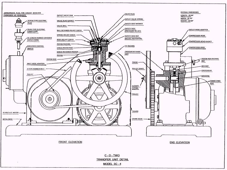
Figure 3-1.\C-O-TWO Transfer Unit. starter arrangements. This model was previously manufacturered by two companies, the C-O-Two Fire Equipment and the Norris Fire and Safety Equipment. The SC-5 motor is mounted on a sliding, adjustable base so that its position maybe altered to take up any slack that may develop in the drive belt. The SC-5 pump is a single-cylinder design with a working pressure of approximately 3500 pounds per square inch. This unit has the capability of transferring approximately 80 percent or 38 pounds of carbon dioxide from a fully charged 50-pound supply cylinder. . The pump head is fitted with a flangible safety disc. This safety disc is designed to relieve pressure in the pump at 2650 to 3000 pounds per square inch. The safety disc nut prevents any recoil in the event the safety disc ruptures. As you can see in figure 3-2, the safety disc washer is arranged so you can easily replace it. The lubricating system is an automatic controlled splash type. The oil flow is regulated by a fixed orifice in the oil trough. This action cannot be seen in figure 3-2. A good grade of SAE viscosity #30 automotive oil should be used when you change or add oil. The drive from the motor to the pump is a combination of V-belt drive pulleys and gears. The small gear and large pulley are assembled together as a unit and are both fitted with ball bearings and mounted on the idler shaft. Both pulleys are carefully balanced. A single guard is secured over both gears and pulleys. The motor, furnished as standard equipment, is a 1-horsepower capacitor start induction type. It is suitable for operation on either a 110- or 220-volt, single-phase, 60-hertz circuit. (A dc motor is also available.) An enclosed control switch is located on the side of the motor. INSTALLING AND SERVICING NEW EQUIPMENT After receiving the equipment, you should examine the components for damage. If the unit is damaged, do not attempt to repair it. Return it to the supply officer for reshipment to the manufacturer. Since the oil was drained from the crankcase of the pump before it was shipped to the field activities, be sure to fill it with a standard grade of SAE #30 lubricating oil before you start the unit. On pumps equipped with an oil filler plug and measuring stick, fill them only to the upper groove on the stick. On a unit equipped with an oil cup and no measuring stick, fill it to within one-fourth inch of the top of the cup. Other than the crankcase, only one point on the pump requires lubrication. This point is on the shaft of the idler gear and pulley and is equipped with an Alemite lubrication fitting. In spite of the fact that the pulley shaft was lubricated at the factory, it is advisable to relubricate the area with two or three applications (grease gun shots) of light cup grease before you start the unit. The motor bearings contain enough grease to last for approximately 2 years under average conditions. Before running the pump, you must find an electric circuit compatible to the motor or install one in the shop. Unless otherwise specified, motors are wired to operate on 110-volt, 60-hertz, single-phase circuits. When 220-volt, 60-hertz, single-phase current is available, the hookup of the motor should be rearranged so that it can run on this circuit. A 220-volt wiring diagram is shown on the nameplate of the motor. The plug on the end of the lead conducting the current to the motor from the power outlet should be equipped with a grounding wire, or third wire, which is usually insulated by a white covering. Regardless of whether a three-pronged plug or a pigtail (coming out of the lead near a two-prong plug, fitted with a clip) is used, the system to which you attach this grounding wire must also be grounded to protect the unit. WARNING Before you attempt any work on the electrical circuit, be sure the power source is disconnected. Always "run-in" a new pump or one that has been idle for a long time. This action, accomplished with the CO2 hoses disconnected, is performed as a check for lubrication to make certain that all parts are thoroughly treated. After you turn off the pump, wipe off all excess lubricants. Before you pump carbon dioxide, examine all line connections on both the inlet and outlet hoses. Make certain that all connections between the components are tight. This is important since carbon dioxide is stored under approximately 850 psi at an atmospheric temperature of 70F. Use a slow, steady pull to tighten connections with a wrench no larger than 12 inches in length. Page 3-3.
Figure 3-2.\C-O-TWO Transfer Unit Detail. The transfer unit pumps carbon dioxide in its liquid phase only. This is true of all CO2 transfer units. The amount of liquid carbon dioxide contained in a fully charged cylinder varies with the pressure and temperature; therefore, a standard 50-pound cylinder contains approximately 38 pounds of carbon dioxide in its liquid phase and approximately 12 pounds in its gaseous phase at an atmospheric temperature of 70F. Therefore, the cooler the supply cylinder and the cylinder being recharged, the more efficient the operation of the transfer unit. Consequently, all cylinders should be kept in the coolest location possible. Conversely, the time required to charge an empty cylinder increases with increased temperature of the cylinder. When recharging a smaller cylinder, we found that if you invert the cylinder during the recharging period, it remains cooler and fills faster than it would if placed in an upright position. Larger cylinders should be placed horizontally on the scale when they are being recharged. After all the liquid carbon dioxide is transferred from the supply cylinder, which is approximately 80 percent of the net contents, the transfer of CO2 to the cylinder being recharged stops. After this, another fully charged supply cylinder must be used to finish recharging the cylinder to its full-rated capacity. The majority of gas remaining in the other supply cylinder can be used when you recharge another empty cylinder. The gas transfers itself under its own pressure until the pressure in both cylinders is equal. This method is called cascading. Through this method, the most economical use of the contents of the supply cylinder is made. To prevent expansion of carbon dioxide in the supply hose, and consequently blocking the hose with CO2 "snow," you should use a valve with an outlet opening of at least one-eighth inch in diameter-preferably three-sixteenths of an inch. Standard supply cylinders in 50-pound sizes are obtainable with or without a syphon tube. When you order cylinders, specify the ones with a syphon tube. Those without syphons must be inverted during the transfer process. |
 
|
|
|
|
|
Integrated Publishing, Inc. - A (SDVOSB) Service Disabled Veteran Owned Small Business
|