Custom Search
|
|
  |
|
|
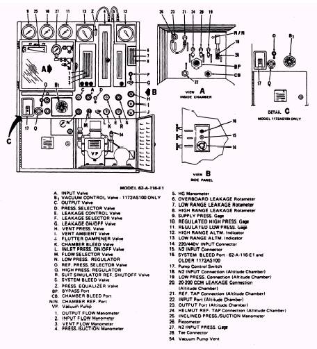
Bell Jar Leakage You may also have problems with the bell jar. The bell jar is used for testing components having more than one possible area of leakage. The bell jar consists of the bell jar itself, a relief valve with a range of 5 to 15 psig, and a bell jar coupling. The relief valve is designed to be leakproof at 5 psi and set to relieve at 10 psig. To perform the leakage test on the bell jar assembly, proceed as follows: 1. Remove hose assembly 3 and nipple assembly 14 (figure 1-5) from the bottom bell jar coupling C-1. Disconnect the opposite end of the hose from differential pressure connection NIP-7. 2. Ensure differential pressure bleed valve V-7, test-pressure-gage-to-bell-jar valve V-2, and system bleed valve V-5 are closed. Open differential pressure shutoff valve V-8. 3. Place the bell jar on the fixture and secure it with a clamp. Plug bell jar top coupling C-2. 4. Slowly open oxygen supply valve V-6 until 100 in. H 2O is indicated on differential pressure gage DF-1. Close valve V-6. Leakage, indicated by a drop in pressure on DF-1, shall not be more than 2 in. H2O in 10 minutes. 5. Close the oxygen supply cylinder valve and open system bleed valve V-5 to bleed the system. CAUTION When the test stand is secured, all valves with the exception of system bleed valve V-5 will be closed. Valve V-5 is left open to prevent accidental build-up of pressure in the system. 6. Secure all test stand valves. Leave system bleed valve V-5 open. REPAIRING AND REPLACING PARTS Anytime you have a defective or damaged part, it must be repaired or replaced. Information on part numbers can be found in the NAVAIR 17-15BC-20 manual. You may on occasion find you have a defective piece of tubing. To replace any tubing installed on this test stand (59A120), remember that you are dealing with high-pressure oxygen. Therefore, you must use tubing with a minimum wall thickness of 0.049 to replace any defective tubing. This tubing may be cut to length and flared to replace any defective portion of tubing. WARNING When you work with oxygen systems, never use any parts that have been in contact with oil, grease, or any other material that is not approved for use in the presence of high-pressure oxygen. Fire or explosion may result when even the slightest trace of combustible material comes in contact with pressurized oxygen. Heat Exchanger Panel If the heat exchanger panel is defective, it may be replaced. You may replace the panel by disconnecting its connections and removing it's seven retaining screws. If a new heat exchanger is used, you may drill or punch holes not exceeding 11/32 inch in diameter in the perimeter, beyond the outer seam welds, for use in mounting. When the holes are drilled at installation, you should be careful to prevent the drill from puncturing the seam welds. Lubrication The test stand nor its components require lubrication. CHAPTER 2 OXYGEN COMPONENT TEST STAND (1172AS100) The 1172AS100 oxygen test stand shown in figure 2-1 is the key to proper testing of oxygen rigger can easily accomplish this by periodically readings, the test stand for leaks and performing safety hazard. To ensure this equipment is in proper operating order is the responsibility of the senior parachute rigger. The senior parachute uses excessive nitrogen, and can be a testing regulators. A leaky test stand gives improper daily preventive maintenance.
Figure 2-1.\Controls and indicators for oxygen system components test stand model 1172AS100. |
|
|
|