Custom Search
|
|
  |
|
|
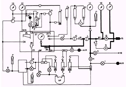
REGULATED HIGH-PRESSURE SYSTEM This system supplies regulated high-pressure nitrogen to the following valves, gages, and connections, as shown in figure 2-4. High-Pressure Regulator (Q) Regulated High-Pressure Gage (10) Regulated Low-Pressure Gage (11) Gage Guard that protects the Low-Range and High-Range Leakage Rotameters. (Although this is not part of this system, the pressure is allowed to enter through the gage guard set at 170 } 5 psig.) System Bleed Valve (S) Vent Pressure Valve (H) Inlet Pressure ON/OFF Valve (L) Tee Connector (inside chamber) (28) N 2 Input Connector (inside chamber) (18) Gage Guard for the N2 input pressure gage (set at 145 } 5 psig) N 2 Input Gage (27)
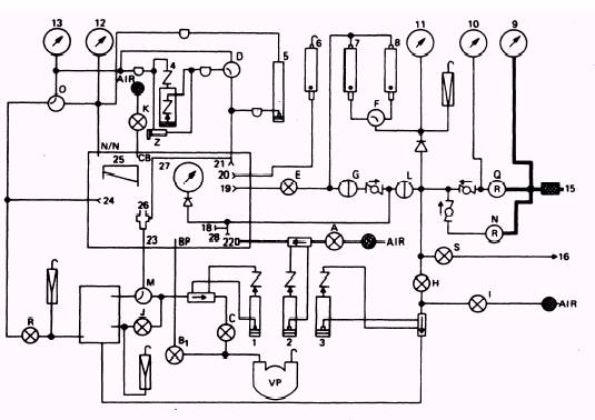
Figure 2-3.\Model 1172AS100 supply nitrogen system. The system has a range of 250 psig to the pressure capacity of the supply cylinder. When you place the high-pressure regulator in the LOAD position, nitrogen flows through the oneway check valve that protects the back side of the high-pressure regulator. This pressure is indicated on the regulated high-pressure gage (10). It then flows through high-pressure lines to the one-way check valve. Pressure continues to flow to the inlet pressure on/off valve and the system bleed valve. (Ensure this valve is closed; if it is open, it bleeds the system.) Pressure also flows to the vent pressure valves and to a gage guard (F) that protects the low-range and high-range leakage rotameters. This gage guard is set to relieve pressure at 170 } 5 psig. The regulated lowpressure gage indicates this pressure although it is not part of the system. When you place the inlet pressure on/off valve in the ON position, high-pressure nitrogen flows to the N2 input connection and the tee connector located inside the chambers. The N2 input pressure gage indicates its gage guard setting of 145 } 5 psig. The regulated high-pressure gage indicates the actual pressure at the N 2 input connection and tee connector. PRESSURIZING THE REGULATED HIGH-PRESSURE SYSTEM To pressurize this system, turn the high-pressure regulator clockwise to the LOAD position until you have the desired pressure. It will be indicated on the high-pressure gage. To check the regulated high-pressure system for leaks, you must first cap the N2 input connection located inside the chamber. Now open the supply cylinder and load the system to 2000 psig using the high-pressure regulator. This is indicated on the high-pressure gage. You should also have a reading of 170 } 5 psig on the regulated low-pressure gage. This is the setting of your gage guard for the protection of the lowrange and high-range leakage rotameters. Close the supply cylinder and note the pressure on the high-pressure gage. After 2 minutes, reread the pressure. If your system is in good working condition, no drop in pressure should occur. With the inlet pressure on/off valve closed, you should have no reading on the N 2 inlet pressure gage. If a pressure is registered, it indicates that you have a leak within one or both of your on/off valves (N 2 inlet or leakage).
Figure 2-4.\Model 1172AS100 regulated high pressure N2-52 system. A pressure drop on the regulated low-pressure gage indicates that the leakage on/off valve is leaking. This completes your leakage check. You must bleed the system by turning the high-pressure regulator to the VENT position until the high-pressure gage reads zero and then open the system bleed valve. This bleeds all remaining lines. |
|
|
|