Custom Search
|
|
  |
|
|
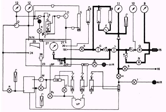
REGULATED LOW-PRESSURE NITROGEN SYSTEM The purpose of the regulated low-pressure nitrogen system is to supply regulated lowpressure nitrogen to the N2 input connection and the in-system leakage rotameters. This system, shown in figure 2-5, has a range of 0 to 180 psig. You adjust the pressure by using the mechanically operated low-pressure regulator. When you open the low-pressure regulator, nitrogen flows through the one-way check valve to the back side of the one-way check valve that protects the high-pressure regulator. As nitrogen enters the high-pressure lines, it flows to the inlet pressure on/off valve, the system's bleed valve, the vent pressure valve, and through the gage guard that protects the in-systems leakage rotameters. (Nitrogen also flows into the rotameters and to the 200- to 230-psig relief valve. However, this is not considered part of the low-pressure system. For the nitrogen to flow to the item under test, you have to open the inlet pressure on/off valve. This allows nitrogen to flow to the input connection inside the chamber where the item under test is connected. PRESSURIZING THE REGULATED LOW-PRESSURE NITROGEN SYSTEM When you pressurize the low-pressure nitrogen system, be sure that the N2 input connection is capped and the supply cylinder valve is open. Turn the leakage selector valve to the HIGH position and the pressure selector valve to the HG position. Turn the inlet pressure and leakage on/off valves to the ON position. Slowly turn the low-pressure regulator clockwise until the regulated low-pressure gage and the N2 input gage indicate 70 psig. (We use 70 psig because this is the pressure used to calibrate the rotameter system.) At this time, return the inlet pressure on/off valve to OFF. There should be no leakage; but if any leakage occurs, the small ball in the high-range leakage rotameter tube will rise.
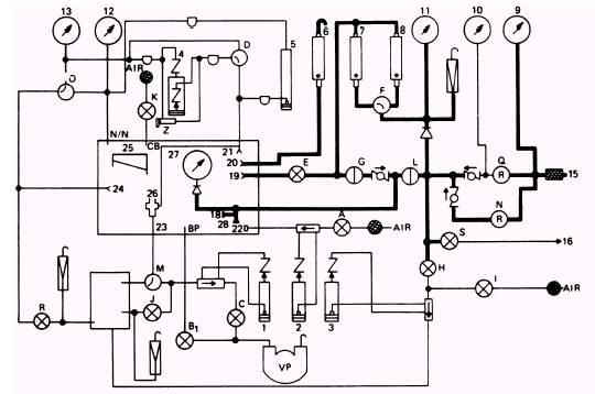
Figure 2-5.\Model 1172AS100 regulated low pressure N2 2-6 system. Turn the leakage selector valve to LOW RANGE. No leakage should be indicated on the low-range rotameter. Return the leakage-selector valve to HIGH RANGE and the inlet pressure on/off valve to the ON position. Slowly open the low-pressure regulator until the regulated low-pressure gage indicates 160 psig. (The N2 input pressure gage should read its gage guard pressure of 145 } 5 psig). Turn the inlet pressure on/off valve to OFF. No leakage should be indicated on the high-range leakage rotameter. Turn the leakage selector valve to the LOW-RANGE position. No leakage should be indicated on the low-range leakage rotameter. Use the system bleed valve to decrease the pressure to 70 psig. You must turn the low-pressure regulator counterclockwise until 70 psig is maintained. Leave the test stand in this condition; it is set up for you to perform your next leakage test. ROTAMETER SYSTEM The purpose of the rotameter system is to determine leakage or to make adjustments to items that require bleed adjustments, such as the 20004 miniature regulator. The system consists of two in-system rotameters and one overload rotameter as shown in figure 2-6. The source of pressure for the in-system rotameters is the low-pressure regulator (N). You receive your source of pressure for the overboard rotameter from the item under test. PRESSURIZING THE ROTAMETER SYSTEMS To use the rotameter system, turn the inlet pressure on/off valve (L) to ON. NOTE: Before you pressurize the rotameter systems, be sure the leakage selector valve (F) is in the HIGH position. This valve should always be in the HIGH position unless you are using the low-range rotameter to read low readings. Turn the leakage on/off valve (G) to ON and the inlet pressure on/off valve to OFF. Look at your high-range leakage rotameter. If no leakage is indicated, turn your leakage selector valve (F) to the LOW RANGE position. Check your low-range leakage rotameter for leaks. In both leakage tests if the small ball rises in the
Figure 2-6.\Model 1172AS100 rotameter system. rotameter tube, it indicates a leak. If no leakage is indicated during this test, continue. Return the leakage selector valve (F) to the HIGH position and turn the leakage on/off valve (G) to the OFF position. By slightly cracking the cap at the N2 input connection, you can bleed any pressure indicated on the N2 input pressure gage (27) At this time, a line with two bayonet fittings must be attached between the low-pressure connection (19) and the 200-CCM leakage connection (20) inside the chamber. This line is used to check for any leakage through the leakage control valve (E). Leakage is indicated on the overboard rotameter (G). If no leakage is indicated, remove the side attached to the leakage connection (20) and attach it to the reference tap connection (21 ). (This sets your test stand up to perform the differential pressure system test.) The reference tap connection (21) is also located inside the chamber. Place a cap over the piezometer and turn the pressure selector valve (D) to the H2O position. Slowly open the leakage control valve (E) until the pressure/suction manometer (4) indicates 9.0 inches of water (in. H 2O). Fully closing this valve (E) may be necessary after you reach 9.0 in. H2O. No leakage should be indicated on the high-range leakage rotameter (8). Turn the leakage selector valve (F) to the LOW RANGE position. No leakage should be indicated on the low-range leakage rotameter (7). Close the leakage control valve (E) and turn the leakage selector valve (F) to the HIGH RANGE position. Now disconnect the line at the low-pressure connection (19). Bleed the pressure from the pressure/ suction manometer (4); then reconnect the lines. If you find this system has no leakage, your test stand is set up to perform the differential pressure indicating system leakage test. |
 
|
|
|
|
|
Integrated Publishing, Inc. - A (SDVOSB) Service Disabled Veteran Owned Small Business
|