Custom Search
|
|
  |
|
|
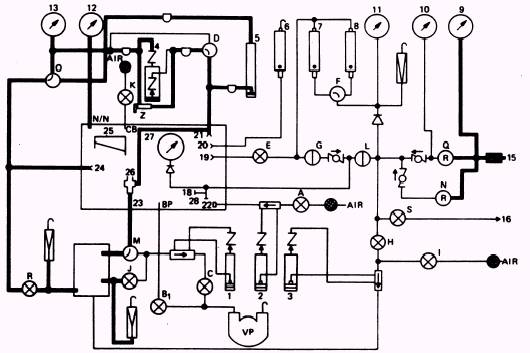
DIFFERENTIAL PRESSURE INDICATING SYSTEM The schematic for the differential pressure indicating system is shown in figure 2-7. The purpose of this system is to sense the difference in pressure between the outlet of the component being tested and the surrounding atmosphere, whether at sea level or altitude. You use this system when you perform safety-pressure, pressure-breathing, and flow-suction tests. Three manometers on the test stand indicate differential pressure: the pressure/suction manometer (4), the HG manometer (5), and the inclined pressure/suction manometer (25). With the pressure selector valve (D) in the H2O position, pressure or suction is sensed in the
Figure 2-7.\Model 1172AS100 differential pressure indicating system. piezometer (26) by a line that runs from the reference tap connection (21) to the piezometer (26). The pressure/suction manometer (4) registers that pressure or suction. The pressure alS O registers on the HG manometer (5). NOTE: The HG manometer (5) receives pressure or suction from the piezometer regardless of the position of the pressure selector valve (D). From the pressure/suction manometer (4), the pressure flows through another line trap to a connection at the low-range altimeter (13). It then flows to the reference pressure selector valve (O). With the valve (O) in the ALTITUDE CHAMBER position, differential pressure is transmitted to the chamber reference port (N/N). Other valves and connections that affect readings on the pressure/suction manometer (4) are the helmet reference tap (24), the suit simulator reference shutoff valve (R), and the pressure equalizer valve (Z). The helmet reference tap (24) is used when you test the full pressure suit helmet. It gives the differential pressure between the respiratory section and the suit section. When you test the full pressure suit controllers, the suit simulator shutoff valve (R) is used in conjunction with the reference pressure selector valve (O) to give the actual altitudes within the suit. The pressure equalizer valve (Z) equalizes the pressure in the pressure/suction manometer (4) as does the pressure selector valve (D) when the pressure selector valve is placed in the HG position. PRESSURIZING THE DIFFERENTIAL PRESSURE INDICATING SYSTEM NOTE: At this point, knowing that 1.0 psig = 27.7 in. H2O or 2.0 in. HG will be helpful to you. To use the differential pressure indicating system, open the leakage control valve (E) until the pressure/suction manometer (4) indicates 16.0 in. H2O. Place the leakage selector valve(D) in the HG position. Now close the leakage control valve (E). The system should now be maintaining 16.0 in. H2O. If the system has a leak, the high-range flowmeter (8) or the low-range flowmeter (7) will indicate it. If the system has no leakage, disconnect the line between the low-pressure connection (19) and the reference tap connection (21); then remove the plug from the piezometer. To bleed the system, back out on the low-pressure regulator (N) and open the bleed valve (S). After you bleed the system, close the system bleed valve (S). Leave all valves and connections in their present position. Now you are ready to check the vacuum system. VACUUM SYSTEM # This system (figure 2-8) is used to evacuate the chamber to simulated altitudes. It also allows you to draw flows from any item that you have under test. The vacuum pump is considered the heart of the test stand. It is equipped with a vent that is provided to remove any corrosive vapors from the oil used in the pump. Use MIL-L-83767, Type I. Two valves work in direct conjunction with the pump: the vacuum control valve (Bl) and the output valve (C). The vacuum control valve (Bl) will directly evacuate the chamber to any simulated altitude necessary to test oxygen components. The output valve (C) draws a flow through the item under test. By using the output valve (C), you can draw a flow through the item under test, through the piezometer (26), the flow selector valve (M), the output vol-o-flo element, and into the vacuum pump. When you place the selector valve (M) in the SUIT SIMULATOR position and open the flutter dampener valve (J), the flow is identical to the flow that occurs when you use the output valve (C), except the flow is drawn through the suit simulator tank. |
|
|
|