|
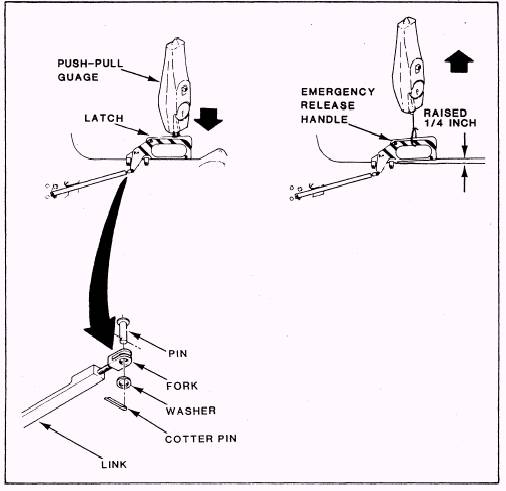
Emergency Release Handle Assembly Check-Out The emergency release handle assembly check-pull-test tools. You should raise the safe/ arm out may be divided into nine major steps. Portions of the test are shown in figures 6-45 and 6-46. 1. Install the initiation pull-test tool set. Lower the emergency release handle and the safe/ arm control to the DOWN and LOCKED position. Position the push-pull gauge against the top of the emergency release handle and press down on the latch. You should be able to retract the latch with a maximum of 15 pounds of force. 2. Depress the locking latch and raise the emergency release handle one-fourth inch. Attach a push-pull gauge and lanyard to the emergency release handle and pull up and aft. The handle should rotate fully with a maximum force of 40 pounds. You should also notice that seat release shaft rotation actuates the seat and man separa-tion sear, and the pull-test tool extends to the relaxed position. Check to see that the T-bar blocks the firing control rotors, and the emergency
3. Lower the emergency release handle to the full DOWN and LOCKED position. Watch the seat and man separation sear return to the ARM position and the T-bar disengage from the firing control rotors. 4. Raise the safe/ arm control to the full UP and LOCKED position. Squeeze the emergency
release handle and slowly pull up and aft. Notice that the connect and disconnect upper sear does not move. Lower the emergency release handle to the full DOWN and LOCKED position.
5. Grasp the emergency release handle and, without squeezing the handle or releasing the lock-ing latch, pull up on the handle. The handle should not move.
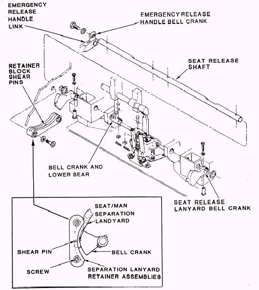
6. Remove the clevis from the fork at the connect and disconnect sear. Remove the top screws and loosen the bottom screws on the lanyard retainer assemblies. Rotate the retainers release handle is locked in the UP position. forward.

Figure 6-45.- Emergency release handle assembly check-out.
7. Lower the safe/ arm control to the DOWN and LOCKED position. Simulate a seat/ man separation by unlocking the emergency release handle. Pull upon both the seat and man separa-tion lanyards. Observe that the seat release shaft rotates to the released position and the seat/ man separation upper sear moves downward. You should also notice that the seat/ man separation lanyards release from the bell cranks.
8. Attach the seat release lanyards to the seat release lanyard bell cranks. At this point, make sure that the seat release lanyards are not pinched between the seat release lanyard bell cranks and the slots in the lanyard retainer assemblies. Rotate the seat release lanyard bell cranks down below the shear pins in the lanyard retainer assemblies. You should ensure that the lanyards remain attached to the bell cranks. Rotate the lanyard retainer assemblies up and aft and install the top screws and washers. Tighten the bottom screws in the lanyard assemblies. When you apply light hand pressure, you should observe freedom of movement in the bell cranks.
9. Lower the emergency release handle to the DOWN and LOCKED position. Remove the initiation pull-test tool set.

Figure 6-46.- Separation lanyard retainer assemblies.
|

