Custom Search
|
|
  |
|
|
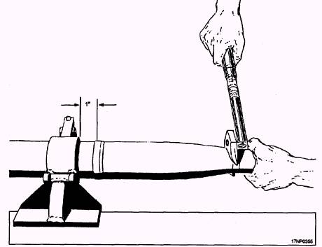
2.75-INCH AIRBORNE ROCKET ASSEMBLY PROCEDURES Unpacking and inspection of the warhead, fuzes, and motor are essentially the same as for the 5.0-inch rocket components discussed earlier in this chapter. Assemble rocket components as follows: 1. Place rocket motor body in holding fixture (fig. 13-25).
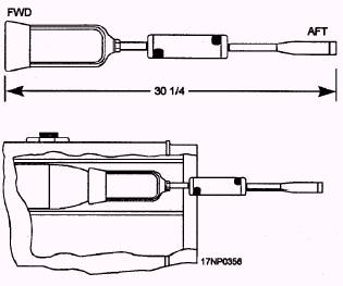
Figure 13-25.-Holding fixture assembly. 13-25 2. Hand tighten warhead to motor. 3. Apply the specified torque to the warhead by using a crowfoot adapter and torque wrench (fig. 13-25). NOTE: Some warheads only require tightening until the warhead seats on the motor 360 degrees. 4. Install fuze hand-tight in the warhead. 5. Verify there is no gap between the fuze and warhead or warhead and motor. 6. Remove assembled rocket from holding fixture. 7. Remove and retain fin protector just before inserting rocket into launcher. 8. Slowly push the rocket into the tube by using rocket loading and release tool (fig. 13-26) until detent snaps into position in detent groove.
Figure 13-26.-Rocket loading and release tool.
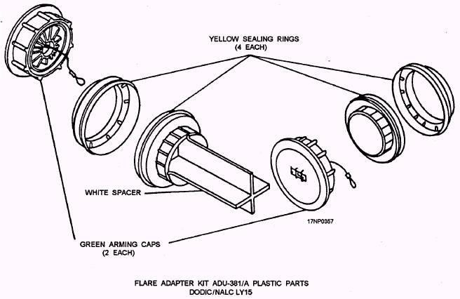
Figure 13-27.-Flare adapter kit. CAUTION When installing Mk 34 and Mk 63 warheads, use the chain wrench only in the area indicated by the decal. This prevents damage to the warhead. NOTE: A groove may be cut in one nylon insert only of the practice warheads Mk 6 Mod 7 and Mk 32 Mod 0. This facilitates assembly of the warhead to the motor. For detailed information concerning the assembly procedures of airborne rockets, you should refer to Airborne Rockets, NAVAIR 11-85-5; 5.0-Inch Airborne Rocket Launchers LAU-10 Series, NAVAIR 11-75A-63; and 2.75-Inch Airborne Rocket Launchers, NAVAIR 11-75A-61. |
 
|
|
|