Custom Search
|
|
  |
|
|
5.0-INCH AIRBORNE ROCKET ASSEMBLY PROCEDURES The following 5.0-inch airborne rocket assembly procedures are used when you load the LAU-10 airborne rocket launcher. The LAU-10 airborne rocket launcher is discussed in chapter 2 of this TRAMAN. If the rocket launcher is being reused, it must be sent to AIMD for electrical checkout prior to loading. The 5.0-inch rocket components maybe received as follows: The rocket motors are preloaded in the 4-round LAU-10 launcher, and the fuze and warhead are shipped in separate shipping containers, or all rocket components are shipped in separate authorized shipping containers. Unpacking Rocket Components Rocket motors and other rocket components are unpacked as discussed in the following steps: WARNING Banding straps are under tension. You must use care in cutting them to prevent injury. 1. Open wooden shipping crates by using hand tools, such as shears or steel strap cutters. Cut or untwist the securing wires from the metal containers with shears or pliers. Remove the end pans from the launcher shipping containers. 2. Keep all containers in a horizontal position while opening them. During the assembly procedure, keep the rocket warheads and motors in a horizontal position. This decreases the possibility of accidents. 3. All retrograde items, such as metal boxes, wooden boxes, spacers, and thread protectors, are
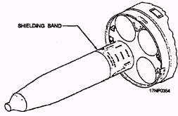
Figure 13-23.-Computer control group installation. removed from the components in preparation for assembly. These retrograde items must be retained and disposed of according to current directives. Inspecting Rocket Components As the rocket components are removed from their shipping containers, inspect them by performing the steps listed below. Dispose of defective items according to current directives. The components you inspect include launchers, warheads, fuzes, and rocket motors, to include their fins. WARNING To avoid personal injury and equipment damage in an operation involving assembly, disassembly, fuzing, defuzing, or cleaning, you must do the work in a designated area. This area must be safely located away from other explosives and vital installations. Only the smallest number of rockets practicable should be exposed. Only authorized personnel essential to the work should be permitted in the vicinity. Refer to the publications NAVAIR 16-1-529 and NAVORD OP 3565 for RADHAZ procedures and precautions. WARHEADS.- Inspect the warheads as follows: WARNING Warheads that are cracked or have a gap between the fuze adapter and the warhead are hazardous. 1. Verify that the warhead is not cracked and no gap exists between the fuze adapter and the warhead. 2. On the Mk 32 warhead, verify that the fuze is staked 3. Verify that the base and fuze cavity threads are not damaged or corroded. WARNING Do not use a warhead that does not have the base fuze hole closed by a steel plug or a base fuze. Base fuzes must not protrude more than l/16 inch. Detonation could occur during handlng or firing. NOTE: Do not disassemble base adapters from the warheads to check for base plugs. 4. Verify that the warhead contains a base fuze or a steel base plug. When installed, ensure the base fuze does not protrude more than 1/16 inch. FUZES.- Inspect the fuze as follows: WARNING Fuzes that are damaged are hazardous. Detonation may occur. CAUTION Do not use Mk 93 or M414 fuzes with nose cones that are completely penetrated by scratches, cracks, or abrasions. Minor scratches or abrasions do not affect their performance or safety. 1. Verify that the fuze body is not damaged. 2. Check the fuze threads for damage or corrosion. ROCKET MOTORS.- Inspect the motor as follows: 1. Verify that the motor tube is not dented, deeply scratched, gouged, or corroded WARNING Use an authorized metal shielding band assembly only. Do not substitute the Mk 71 motor plastic fin retainer band because it offers no RADHAZ protection. NOTE: Rocket motors packaged in individual wooden containers may be received with the old, narrow, metal shielding band (P/N 1516140) installed. This band is obsolete and must be replaced with shielding band assembly P/N 4902192 when unloaded from the launchers. 2. Verify that the shielding band and the RADHAZ barrier are in place. 3. Verify that the nozzle plug is in place. 4. For rocket motor Mk 71, verify that the fin retainer is in place, the fins are not bent or broken and the fin pin is clean and free of foreign matter. The spring-loaded fins must be exercised four to six times. 5. The motor contact bands, motor tube threads, and nozzle and fin assembly must be clean and free of grease or other lubricants. 6. Check threads for damage or corrosion. Assembly of Rocket Components Rocket components are assembled as discussed in the following steps: WARNING Shielding bands must be in place whenever the rocket motor is out of or protrudes from the launcher. Ensure the shielding band covers the contact band but does not touch it. 1. Place detent lift arm in load position. 2. Push forward on aft end of rocket motor until forward end of rocket emerges from launcher. 3. Slide shielding band (fig. 13-24) over motor and hold against forward part of launcher; push motor foward until locking tabs seat in the motor detent grooves and not in the contact band groove. NOTE: A standard rocket assembly tool kit containing crowfoot wrenches, a torque wrench, detent locking wrenches, chain wrenches, and strap wrenches is available for the assembly of 2.75-inch and 5.0-inch rockets. 4. Hold motor with strap wrench. Screw warhead into motor and tighten securely with chain wrench until the warhead seats 360 degrees. 5. Attach appropriate nose fuze and tighten.
Figure 13-24.-5.0-inch rocket RADHAZ and electrostatic protection. 6. Push rocket motor slowly into the tube until aft end contacts aft stop. 7. Rotate detent lift arm to flare position. 8. Push the motor forward hard; pawl will engage groove with audible click indicating positive engagement. |
 
|
|
|