Custom Search
|
|
  |
|
|
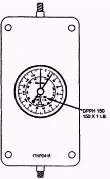
TS-3519/DSM TEST SET SIMULATOR The TS-3519/DSM test set simulator (fig. 16-21) is a portable test set. It is used to simulate a Harpoon missile for wing station checkout, power-on fictional testing, and fault isolation. The TS-3519/DSM is used with the P-3 and S-3 aircraft. AN/ASM-373A AIRBORNE TORPEDO PRESETTER TEST SET The AN/ASM-373A airborne torpedo presetter test set (fig. 16-22) has capabilities for functionally testing the presetter portion of the armament control panel subassembly in the aircraft. It can also be used to check aircraft wiring and the torpedo umbilical connector. The AN/ASM-373A test set is used with the S-3 aircraft. FORCE RETENTION GAUGE The force retention gauge (fig. 16-23) is used to functionally check the bomb rack nose and tail arming solenoids. You should refer to the applicable maintenance instruction manual for the proper retention readings.
Figure 16-23.-Force retention gauge (typical).
2. to ensure that voltage or stray voltage is not present before electrical connection of certain launchers, such as rocket launchers, is made. These two functions are called aircraft release and system control checks. Normally, you perform aircraft release and system control checks before the weapons are installed on the aircraft. However, some checks require the weapons to be loaded on the aircraft. As part of the loading process, the Sparrow, Phoenix, Walleye, and Sidewinder (on some aircraft) weapons are electrically mated to the aircraft. Then, the external power is applied to the aircraft, and a missile-on-aircraft test (MOAT) is performed. This test is normally performed during the prior-to-launch sequence. You conduct the Sparrow and Phoenix MOAT by activating the circuits within the aircraft. Then, you observe the indications as they are received in the cockpit, No test equipment is required to perform this test. The Sidewinder MOAT is performed by at least two team members and a team leader using an audio headset and a TTU-304/E tester. The TTU-304/E tester is basically a pencil flashlight with an infrared filter lens. The person in the cockpit plugs the headset into the audio connection and turns on the switches indicated in the checklist. These switches are Sidewinder COOL, STATION SELECT, and AUDIO CONTROL. The person at the missile station removes the missile protective dome cover. Then, with the tester turned ON, the beam of the tester is moved across the nose of the missile from a distance of 4 to 6 feet. As the missile senses radiation from the tester through the launcher's audio amplifier, a tone is heard in the headset. If more than one missile is loaded each missile should be tested and the dome covers replaced. Sidewinder MOAT may also be performed during pretaxi arming signals with the pilot as the person in the cockpit. The Walleye MOAT also requires at least three persons and a DSM-77 test set. The DSM-77 test set projects a test image to be received by the Walleye. The test image is displayed on the aircraft cockpit monitor. (See figure 16-11.) With the cockpit switches ON, as listed in the checklist, the Walleye dome cover removed, and the tester mounted on the weapon and switched to LIGHT, a display appears on the aircraft monitor. When the tester is switched to LIGHT-MOTION, the image moves from side to side, diagonally, or up and down, depending upon the position of the tester. The tester control assembly is rotated around the foundation assembly during the testing process. During each position test, the person in the cockpit pulls the trigger switch and the weapon's television camera will lock on to one of the target dots and follow it as it moves. As each test is completed for each weapon loaded, the dome cover should be replaced. WARNING During MOAT, or any other test being performed after weapons have been loaded on the aircraft the MASTER ARMAMENT switch must NEVER be placed in the ON position. When performing aircraft release and system control checks, you should always use the step-by-step procedures (checklist) provided in the aircraft loading manual. A few safety precautions must be observed when performing aircraft release and system control checks. These precautions are listed below. 1. Before you begin an aircraft release and system control check, make sure the aircraft is parked in a designated area, secured, and electrically grounded. 2. Before you apply external electrical power to the aircraft, make sure all cockpit switches have been positioned to OFF, NORMAL, or HOLD. If required, apply external air conditioning. 3. Release and control system checks will not be performed with weapons loaded on the aircraft. Checks may be performed with airborne stores (fuel tanks, empty MERs/VERs, pods, etc.) installed on the aircraft stations, provided cartridge retainers, breech caps, and ejector cartridges are removed 4. Test equipment should only be used by personnel who have become qualified through an established qualification and certification program. Stray voltage checks are normally performed with the weapon loaded on the aircraft, but they are made before making an electrical connection between the weapon and the aircraft. Additionally, this check is normally performed after the aircraft's engines have been started and all aircraft preflight checks have been completed. The stray voltage check is performed at the last possible moment before the aircraft takes off. This is to ensure that no voltage has been induced in the aircraft firing circuitry from external sources, such as the ship's radar. The launcher electrical safety pin must not be removed until the aircraft is positioned on the catapult for takeoff. |
 
|
|
|
|
|
Integrated Publishing, Inc. - A (SDVOSB) Service Disabled Veteran Owned Small Business
|