Custom Search
|
|
  |
|
|
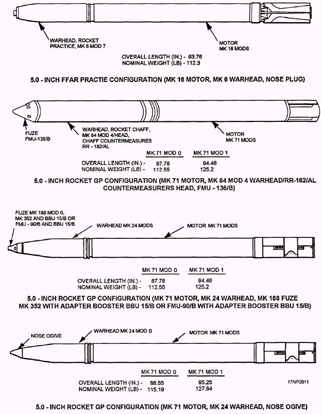
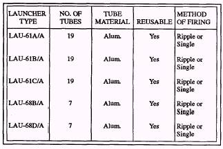
AIRCRAFT ROCKET LAUNCHERS LEARNING OBJECTIVE: Recognize the shipping configuration for aircraft rocket launchers and identify common aircraft rocket launcher components. Aircraft rocket launchers (pods) carry and provide a platform to fire rockets. Launcher design permits multiple loading and launching of 2.75-inch and 5.0-inch rockets. Rocket pods let rocket motors (and, in some cases, completely assembled rounds) stay in the same container from their manufacture, through stowage, to their final firing. Aircraft rocket launchers are classified as either 2.75-inch or 5.0-inch. They may be further classified as either reusable or nonreusable. Launcher tubes that are constructed of metal are considered reusable and are usually returned for reloading. Under certain conditions, they may be jettisoned at the pilot's discretion. Launcher tubes constructed of paper material are designed for onetime use only, and are jettisoned by the pilot after use. The 2.75-inch rocket launchers currently in use are the LAU-61A/A, LAU-61B/A, LAU-61C/A, LAU-68B/A, and the LAU-68D/A. Characteristics and specifications for these launchers are listed in
Figure 2-25.-5.0-inch FFAR (typical configurations). table 2-4. For detailed information about the LAU-61 and LAU-68 series launchers, refer to 2.75-inch Airborne Rocket Launchers, (LAU-61 and LAU-68 series), NAVAIR 11-75A-61. Table 2-4.-2.75-Inch Rocket Launchers
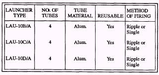
The 5.0-inch rocket launchers are the LAU-10B/A, LAU-10C/A, and the LAU-10D/A. Characteristics and specifications for these launchers are listed in table 2-5. For detailed information on the LAU-10 series launchers, you should refer to 5.0-inch Airborne Rocket Launchers (LAU-10 series), NAVAIR 11-75A-63. Table 2-5.-5.0-Inch Rocket Launchers
SHIPPING CONFIGURATION The rocket launcher shipping configuration shown in figure 2-26 is typical of all launcher shipping configuratioas, except for the RF barriers. Center Section The launcher center section is a cylindrical construction of 4, 7, or 19 tubes held together by a supporting framework, and it is covered with an aluminum skin. The center section houses or supports all other components of the launcher. The center section for the LAU-10 (series) allows either 14-inch or 30-inch suspension. The center section for the LAU-61 and LAU-68 (series) provides for 14-inch suspension only. Shipping Ends The shipping ends are a multipurpose arrangement that consists of a shockpan assembly, a shockpan cover assembly, and/or locking ring assembly. An alternate hole and pin arrangement on the top and bottom is arranged so that the shockpans interlock when the launchers are stacked. The cover is equipped with a rubber seal ring that, when compressed by the locking ring assembly, forms a watertight closure over the end of the launcher. RF Barriers RF barriers consist of a molded, expanded, polystyrene bead base with an aluminum foil coating cemented to the outer surface. RF barriers are used on 2.75-inch pods to prevent the entry of electromagnetic radiation into the rocket igniter circuit. Equally important is the barrier on the aft end of the pod. It prevents exposure of the igniter lead contact. The LAU-61 and LAU-68 use the aft barrier only. The barriers remain installed for flight and are removed by impact or blast when the rocket is fired. |
 
|
|
|
|
|
Integrated Publishing, Inc. - A (SDVOSB) Service Disabled Veteran Owned Small Business
|